The Web Site
The web site is officially up and running! I am definitely not a web page builder, but thanks to some awesome open source software (Open Element) and a very cost effective web hosting company (https://www.hostens.com) who also offer a suite of programs free with the service, www.stclairtech.tech is live.
Eventually this blog may migrate to the www.stclairtech.tech site.
The Manual
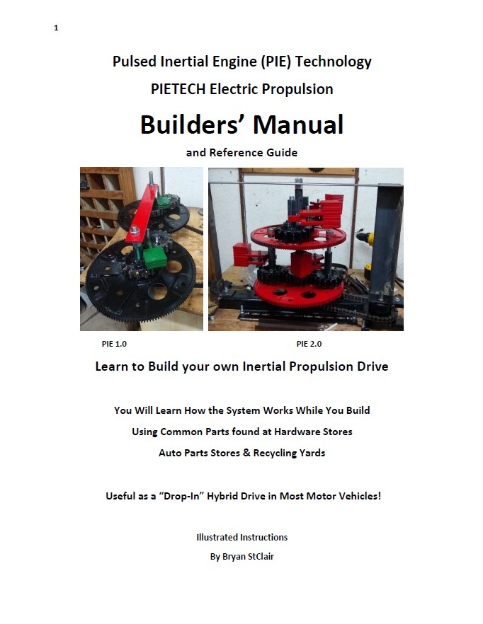
The PIE BUILDER’S MANUAL is complete as well and there are links to it from the stclairtech web site. I have listed it on eBay either as a downloadable PDF formatted e-book or as a paper manual. The paper manual also includes the downloadable version and they both come with links to exclusive manual “companion videos”.
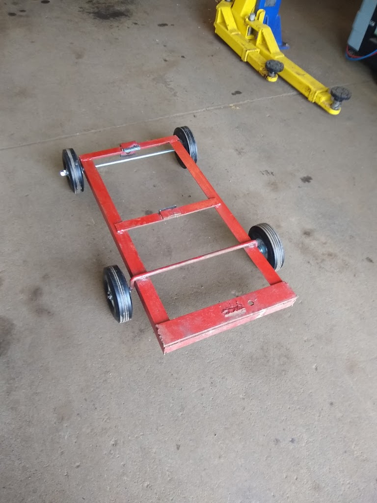
The PIE 4.3
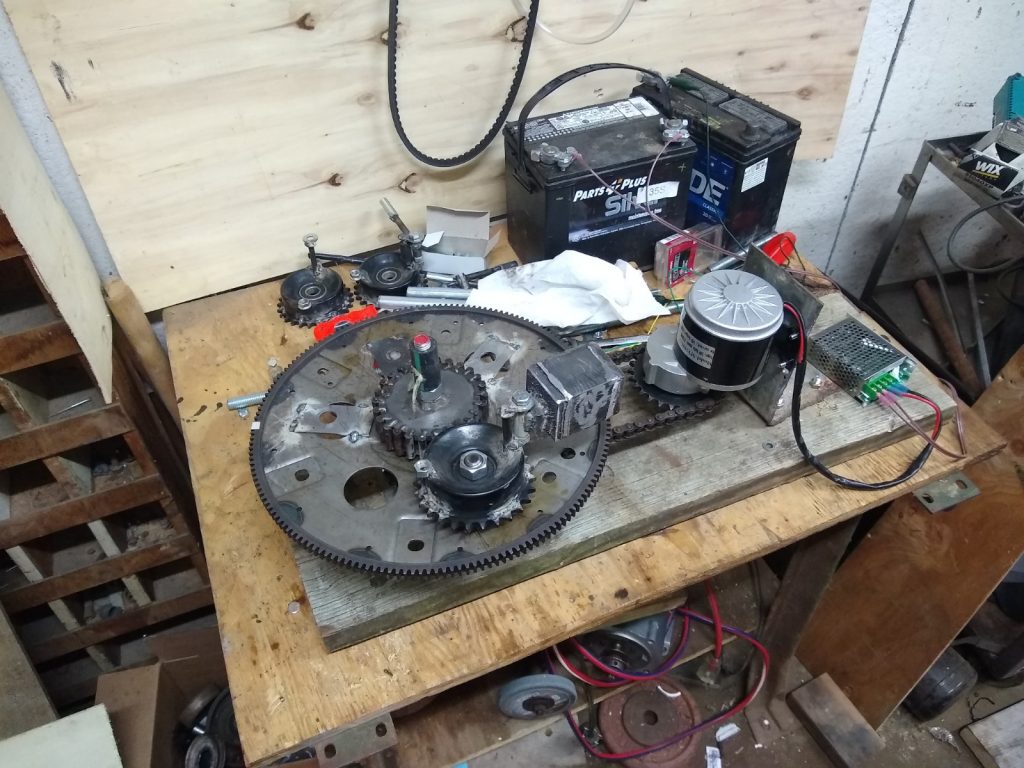
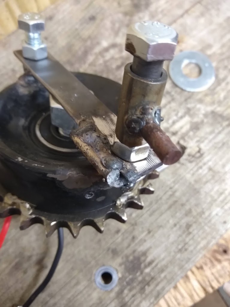
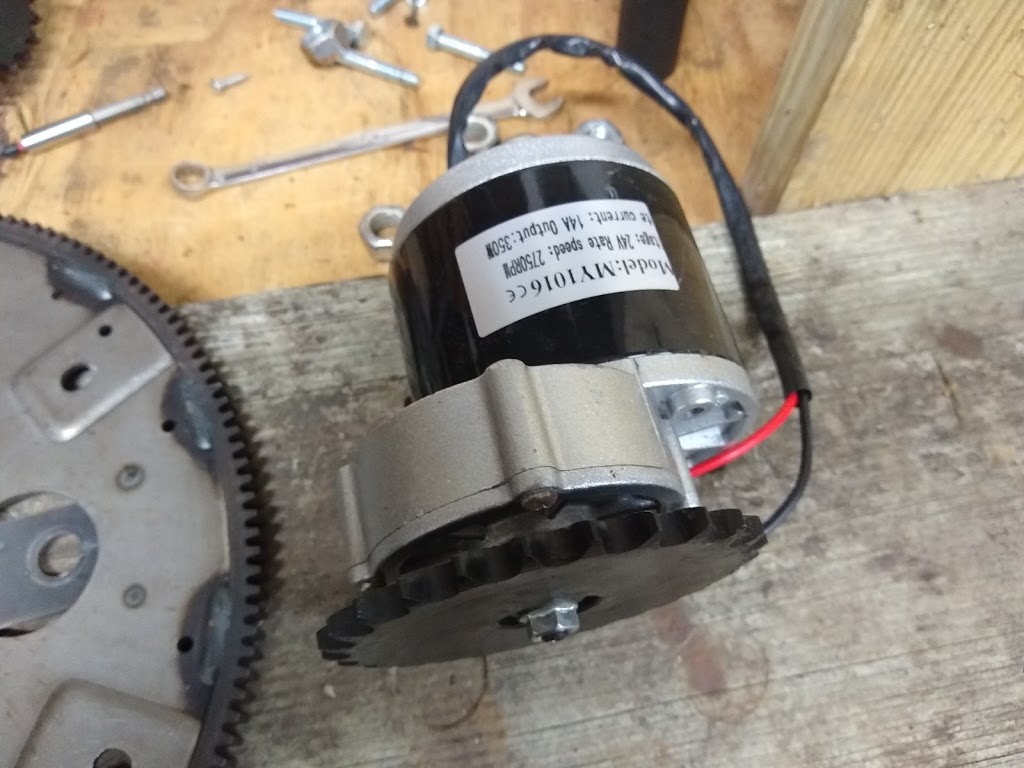
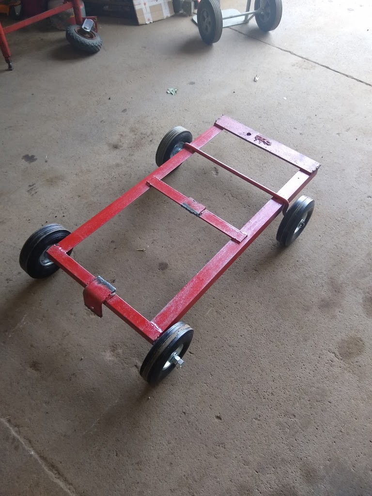
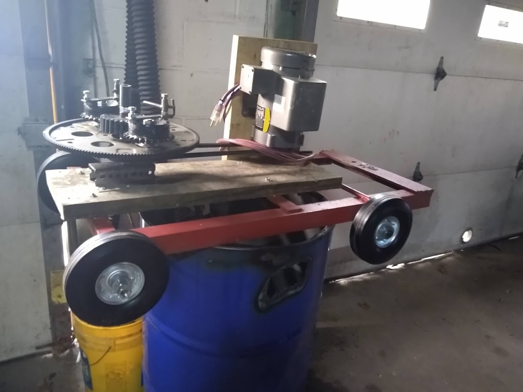
The PIE 4.3 has the new motor installed, and the RPMs are just where I expected them to be. The 24v motor is very strong and seems to do a great job of maintaining a stable speed under load. I thought I was ready to build the second wheel, but building the web site gave me some time to think. There are some modifications and variations I want to explore and experiment with as the building continues.
1st I definitely want to try an odd number of planet gears. One gear works better than tow, so I need to see if that is going to continue to change results as the number of gears increases.
2nd I want to add an electrical circuit to the drive motor that can instantly vary the speed it runs. Since I know that if it is allowed to slow when the weight is leaving the center and accelerating in velocity (power stroke) the thrust is dramatically reduced, it stands to reason that inverting this RPM drop into an RPM increase may lead to better results. This could be somewhat accomplished with matching offset drive sprockets, but I think that faster translations between speeds may be more effective….
3rd I want to increase the efficiency of the weights… But how? The answer to this may have already been answered more than 85 years ago by Mr. Harry W. Bull of Syracuse, NY with a device he called the “Propulsor”. This led to an OMG moment…
OMG Moment:
The H.W. Bull “Propulsor”:
In January of 1935 Harry W. Bull of Syracuse NY was featured in a Popular Science article for his invention known as a “Reaction Motor” which came to be known as the “Propulsor”. This design uses 2 equal weights that are slammed into opposite ends of a tube, one weight hits a solid stop while the other hits a “spring” stop. This creates a differential in the efficiency of the “stopping” of the weights. The solid hit creates sound and heat as waste energies while the “spring” end transmits the directional force more efficiently. Like the difference between a steel and a “dead-blow” hammer.
An interesting chapter in the professional life of Harry Bull is available online at http://epizodsspace.airbase.ru/bibl/inostr-yazyki/iaa/1989/Winter_Harry_Bull_American_Rocket_Pioneer.pdf . On pages 308 & 309 of this volume of a much larger book, the propulsor is briefly discussed.
Of course, Mr. Bull’s work with the Propulsor was immediately rebuffed by the “scholars” of the time and was publicly denounced as a “fallacious” in 1947, just as all other attempts at a reactionless drive have been and still are today.
 |
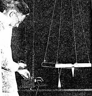
| Harry W. Bull Pendulum Testing |
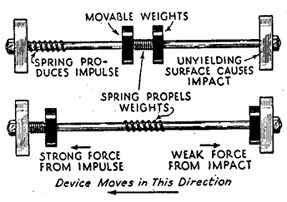 |
| Basic Principal of Propulsor |
Back to PIE 4.3
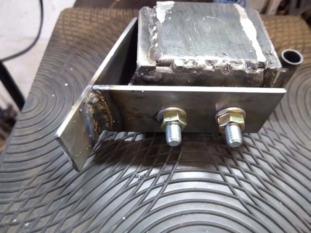
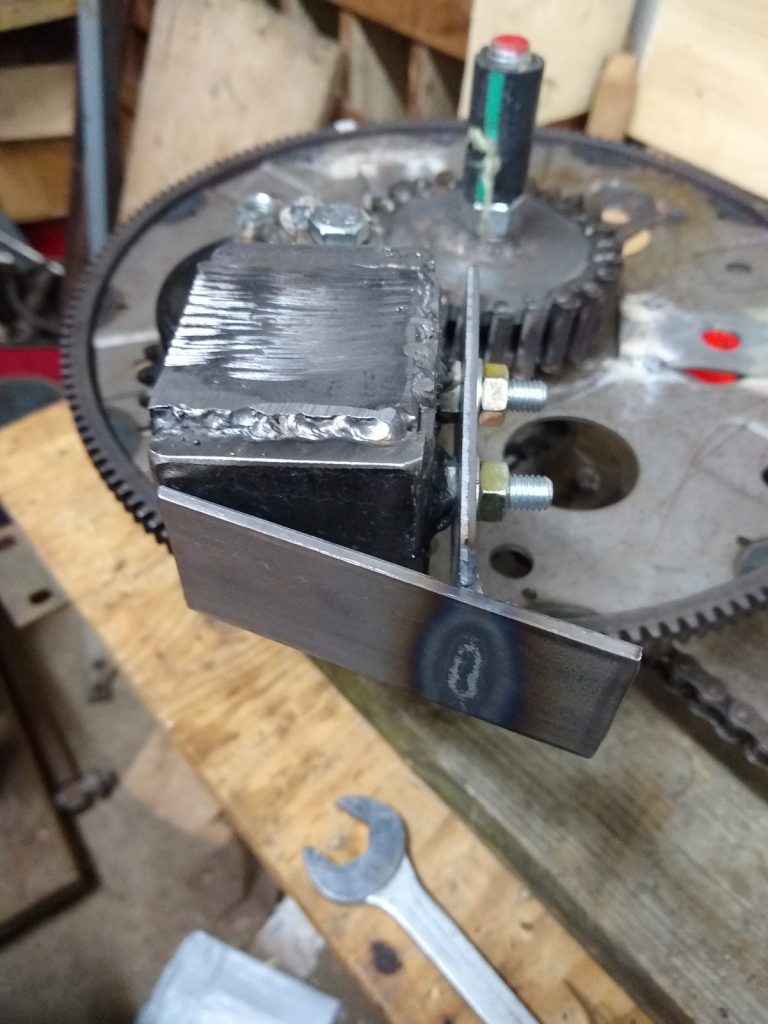
What if the PIE’s weights were “dead-blow”? Since a dead-blow hammer effectively transmits more force in every blow than a plain hammer because it has almost no “bounce-back”, I think that a similar design could be used for the weights which would then transmit their power more effectively with less wasted energy. The reason it transmits power more efficiently is because it lengthens the TIME the contact blow happens! Time, the length of time that virtually any impulse drive uses to produce directional force is a critical feature in successful operation!
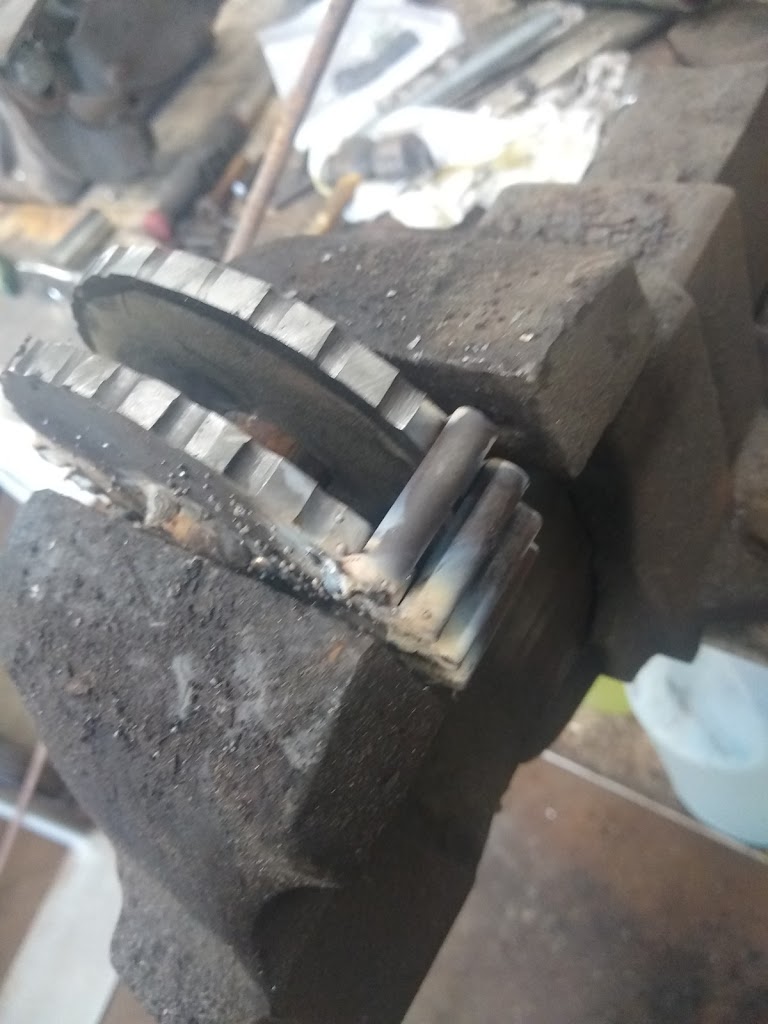
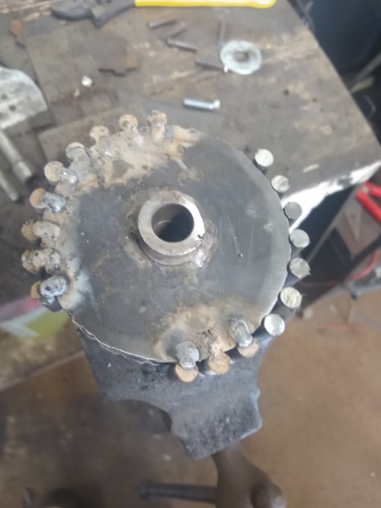
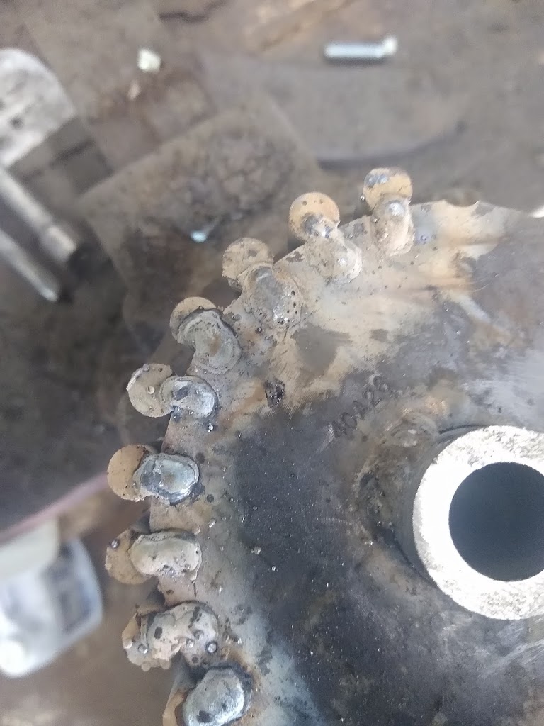
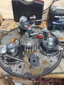 |
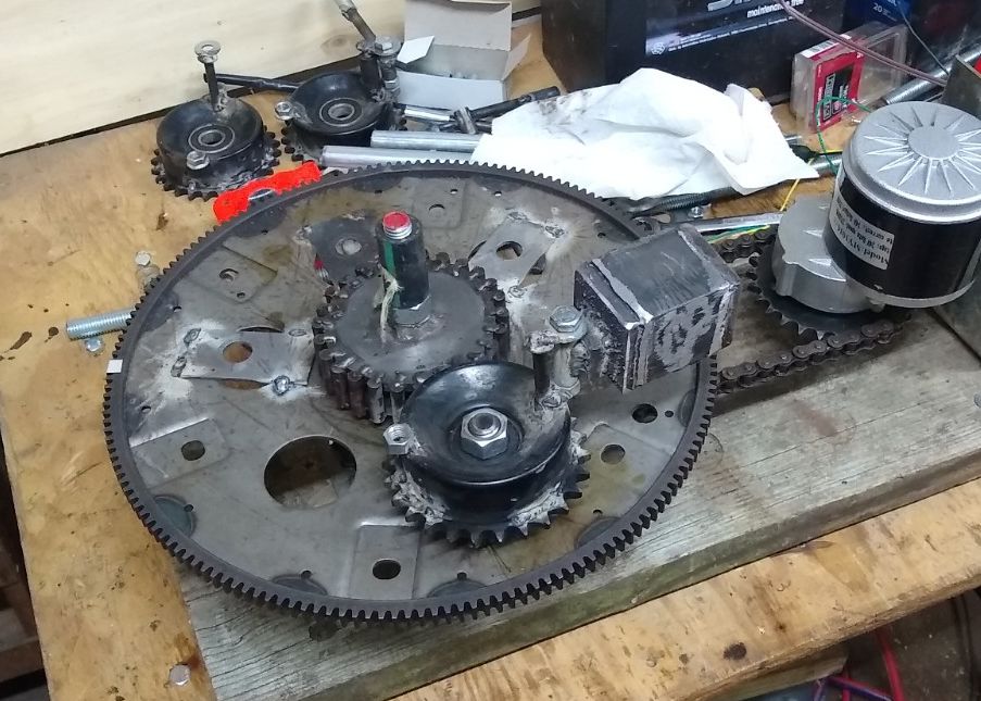
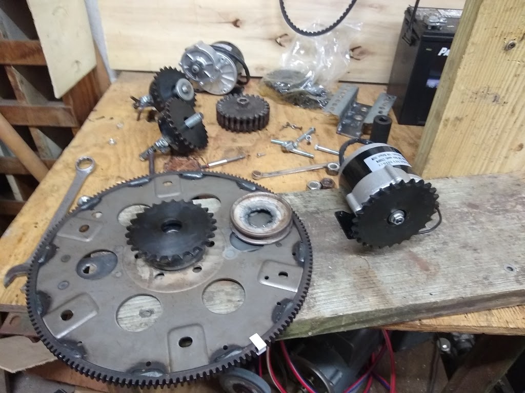
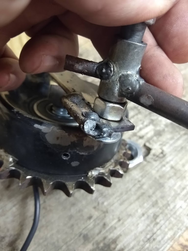
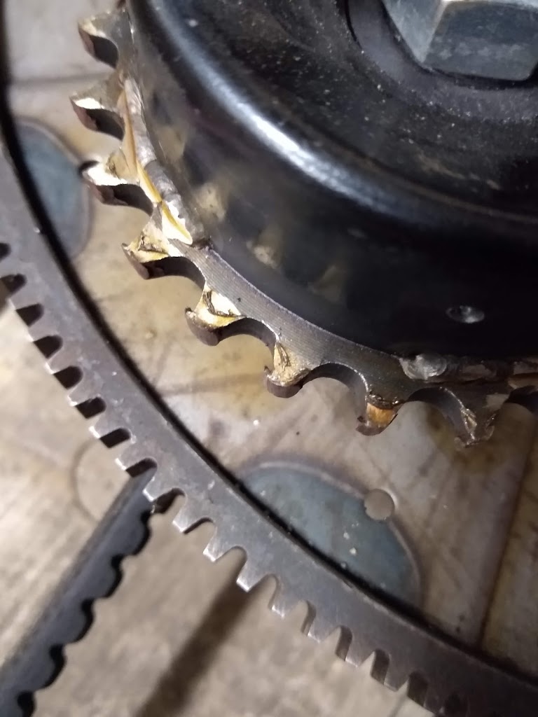
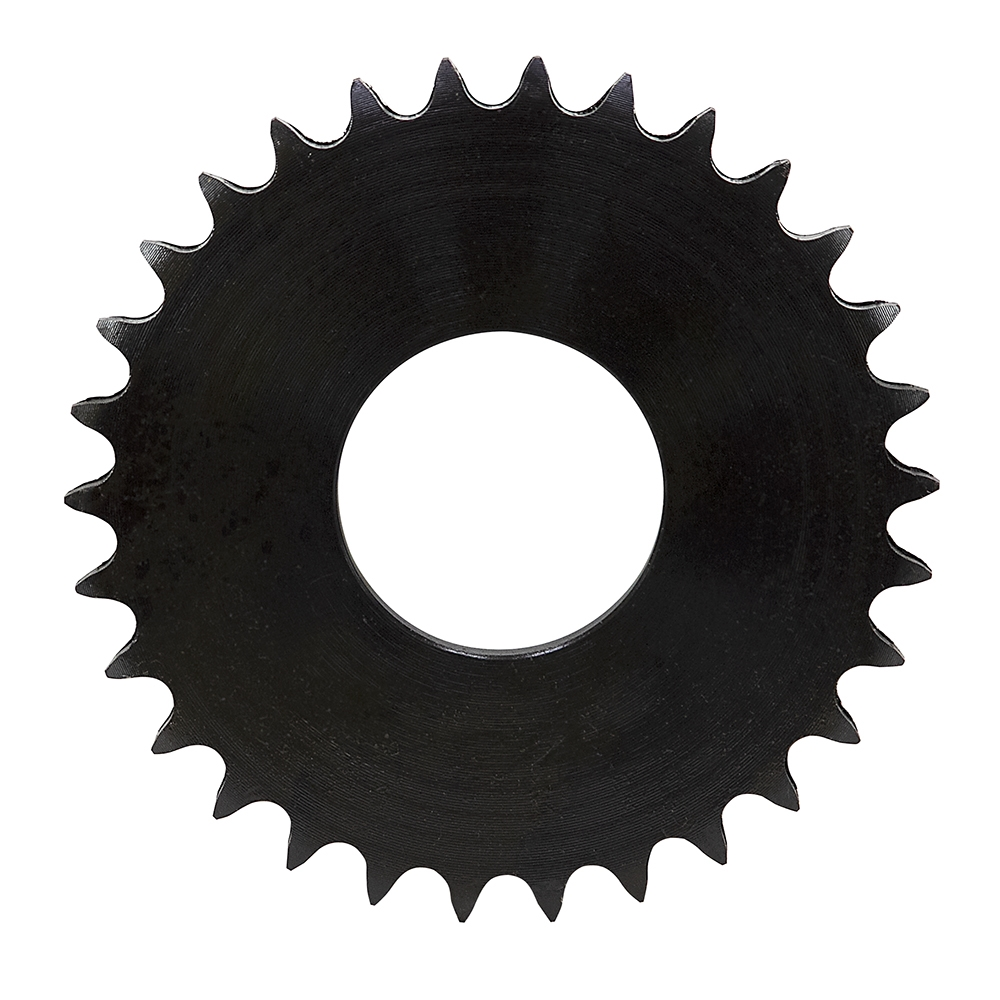
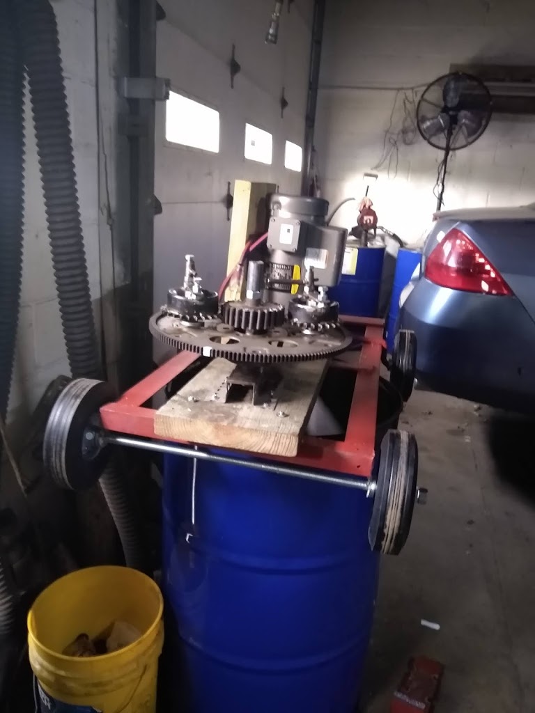
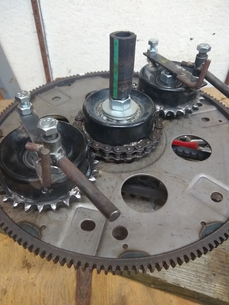
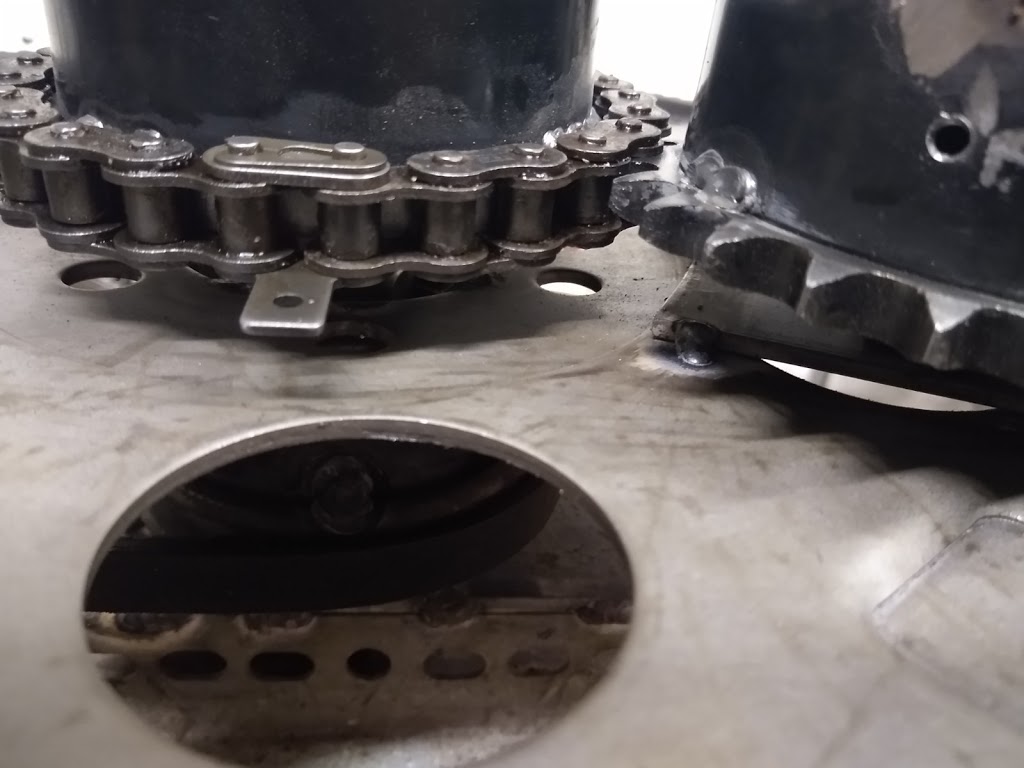
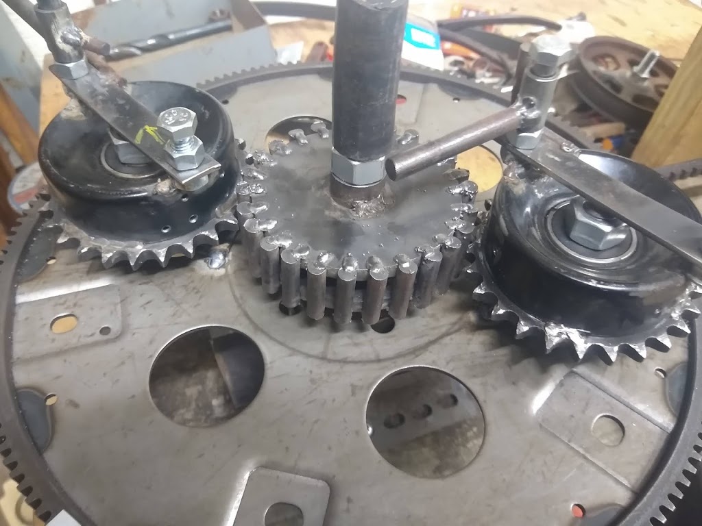
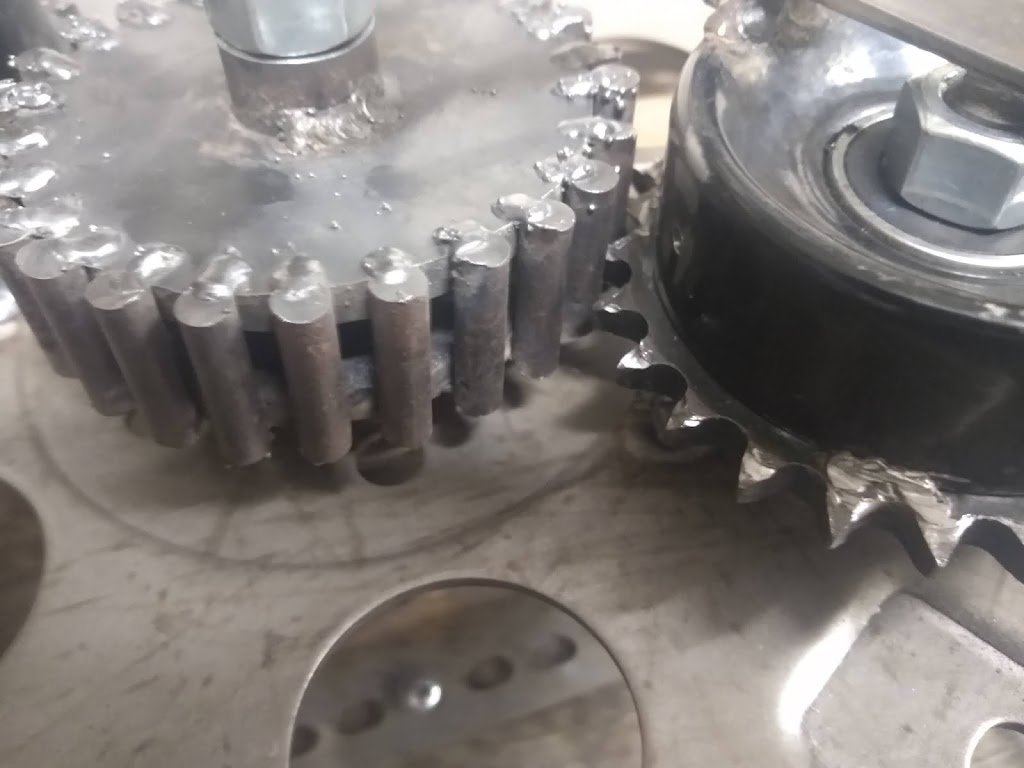
| 3-Planet System |
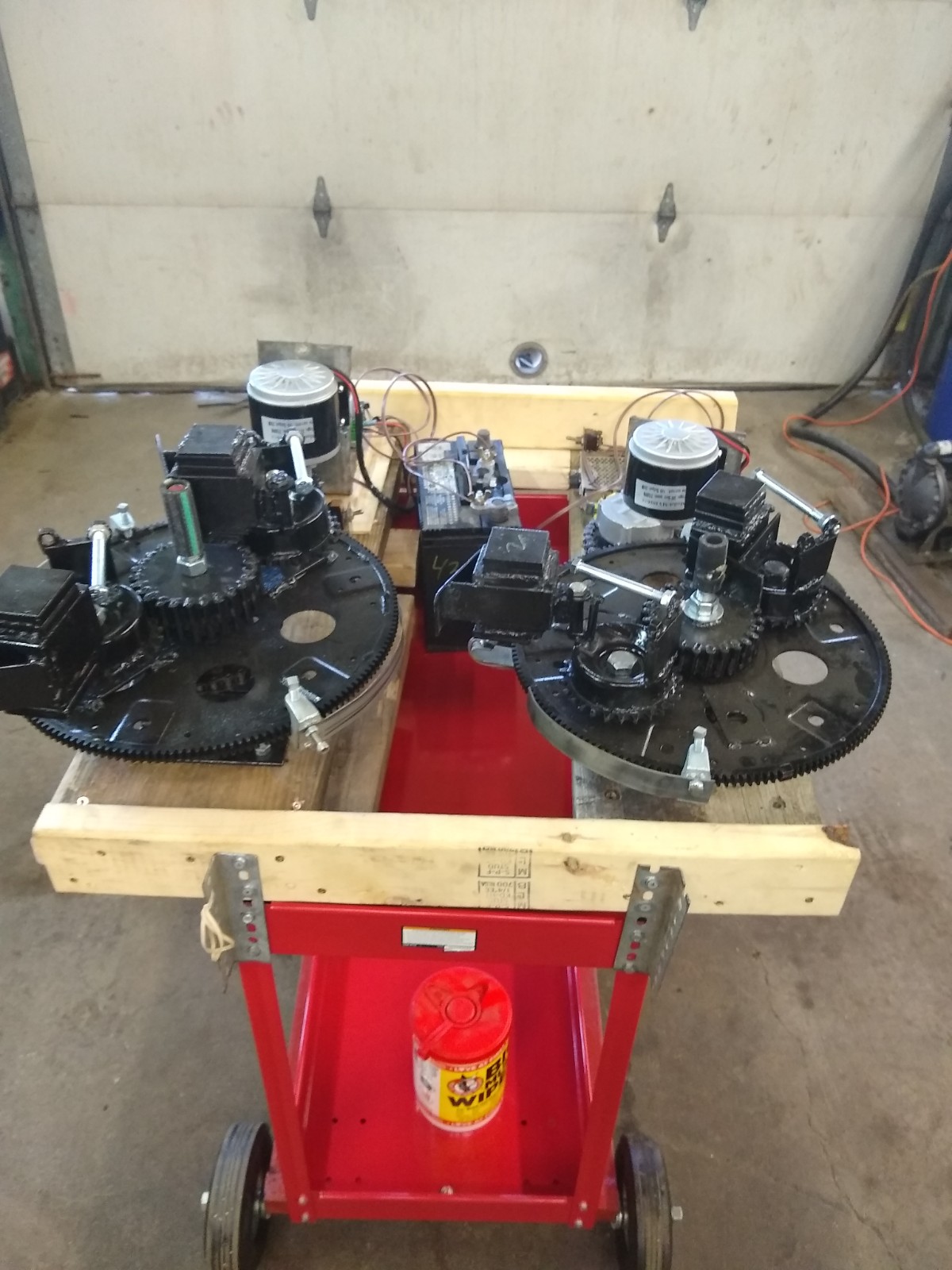
Current Work
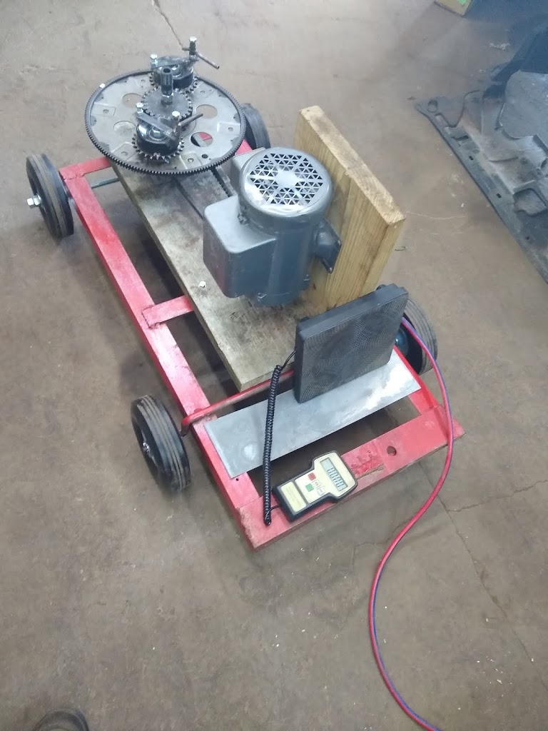
Currently the PIE 4.3 has the option of 2 or 3 planet gears. The 3-gear design just makes sense to me, but testing will tell the story there. There is a motor speed controller currently ordered and I am building more weights to experiment with.
I have just begun testing the 3-planet set-up and I will post more as I go, but there is a video of an initial test run available on YouTube and BitChute (links below).
YouTube: https://www.youtube.com/watch?v=ii1l8W9-8nQ
BitChute: https://www.bitchute.com/video/5pmnbyhLKRcJ/