PIE 4.8 Re-Phased and then Switching to Co-Rotating Design Testing (2 Updates)

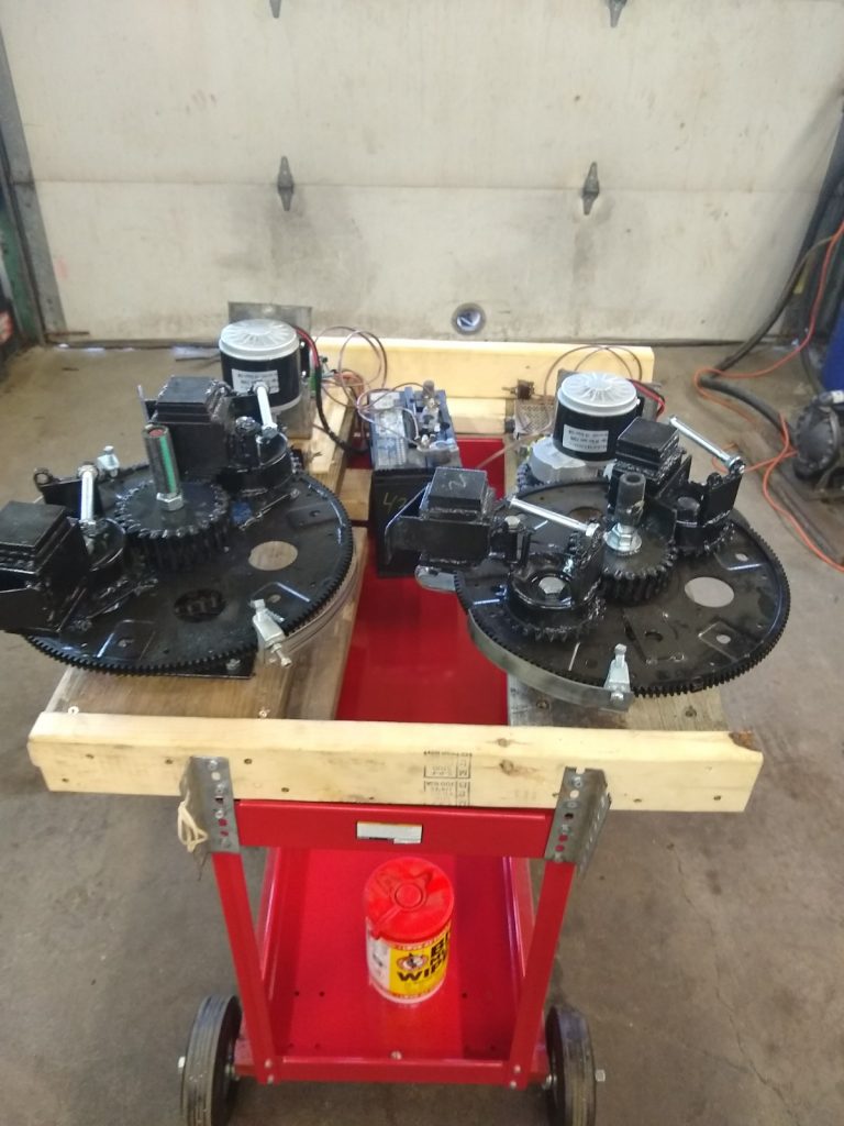
On 7/31/2021 the counter rotating PIE 4.8 was re-phased to have the planet gears synchronized (self-propulsion mode) but then one plant gear was removed from each wheel so that forward pulses will alternate from on side to the other. The non-functioning weights were fastened to the planet gear mounting holes to help balance the wheels a bit.
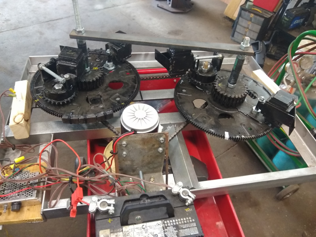
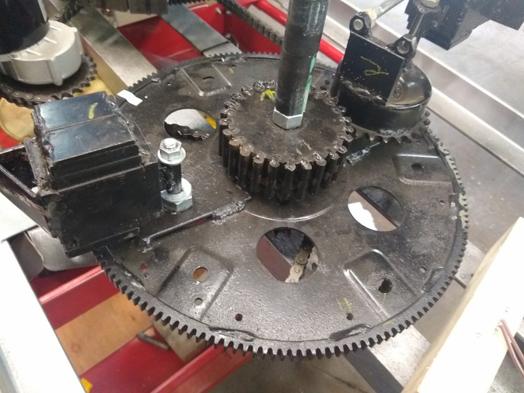
Results were very similar to having all the planet gears and weights in place and operational with road testing showing a 4% to 6% reduction of engine load at the standard speed of 55 MPH with little to no headwind.

I believe this poor performance may be due to the counter-rotating wheels. Previous testing has shown better thrust using co-rotational wheels (rotating in the same direction). It has been suggested that counter rotation might be needed for stability, especially in either an air or space (aerospace) vehicle, but co-rotation should be very possible with proper management using either air foils or gyroscopes. Co-rotation should still be quite manageable a with minimum amount of manipulation.

8/10/2021 Update

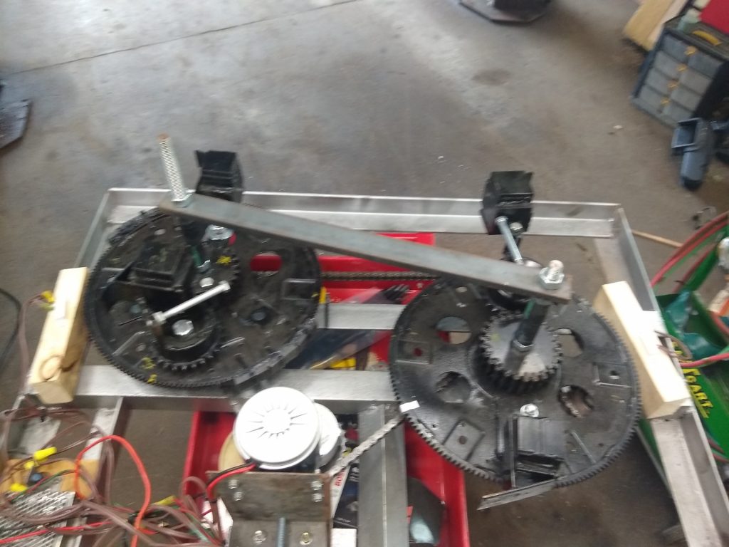
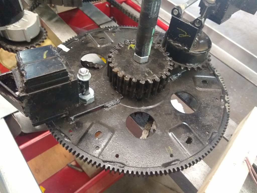
I have now rerouted the chain on the PIE 4.8 so now the Left and Right wheels both turn clockwise, and I have modified the ramp on one of the RH wheel’s weights for the direction change and timed the wheels for self-propulsion (synchronized). With just one weight on the right wheel and two weights on the left wheel I now see that it is a definite improvement over the counter rotating wheel setup!

The first noticeable difference between counter rotating and co-rotating is when counter rotating in this same configuration of 2 weights on left and one on the right the propulsion pulse was strong when a single weight pulsed and weak when two weights synchronously pulsed. With co-rotating wheels the propulsion pulse is strong when a single weight pulsed and doubles in strength when two weights pulse synchronously. In simple terms, the unit is stronger when co-rotational!

I need to put trolley wheels under it again to test properly on the bench, but the unit seems strong and is pulling itself (sliding forward) across the bench when running even without fine tuning the gear timing. Next, I will adjust the gear timing and modify the other weight for clockwise rotation so that I can complete this round of testing.

If there was lots of extra time to do extensive testing it would be best to build it with 4 wheels, two co-rotating and two countering them to be able to arrange them in different ways to record and study the results. I don’t feel it is necessary at this time as the testing I have done is more than adequate to demonstrate the workability of the PIE system.

I have discussed the origin of the SDC and the subsequent positive effects of its use, and when I was setting up the PIE 4.8 to co-rotate, I could visually see the point of heavier motor load in the PIE’s rotation. So I published a short video of this visually obvious effect demonstrating the position in rotation which needs the RPM boost using the Speed Differential Control (below).

More to come soon!!!
PIE 4.8 Changes to SDC and Issues on Latest Test Drive

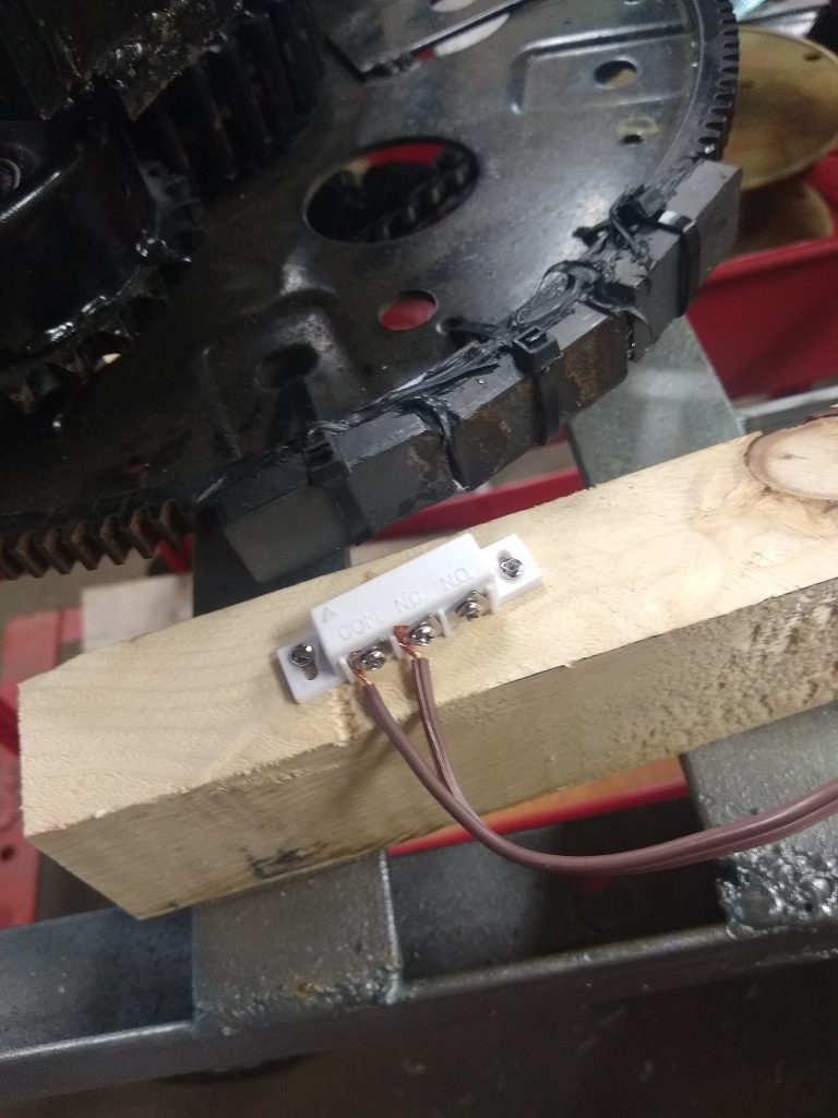
New SDC Switch

It has been a very busy several weeks since I have had opportunity to update this blog. Work and life have been very busy and work on the PIE has been slow.

The re-phased PIE 4.8 has had the first road test completed with no SDC as the SDC micro switch is a continuous source of problems. The lever on the switch tends to break or get bent very easily and the roller wheel also tends to fall off frequently, so it was decided to use a “proximity switch” as a non-contact alternative. The switch chosen is a magnetic switch used for building security systems as a door/window open/close sensor. This is easily activated by mounting magnets instead of mechanical actuators and this works very well.

The PIE 4.8 second test drive was, however, less than outstanding. The re-phased PIE wheels and SDC “should” have yielded much better results than the previously phased tests when it was set up for “self-propulsion”, but the results were very disappointing as the engine load reduction was only in the 4% to 6% range.

I believe it has to do with the counter rotation of the wheels. The “zone of thrust” or “thrust zone” on a single wheel is rather wide as it pulls forward through a good 45 degrees of the rotation, by having the counter rotating wheel, the “thrust zone” is effectively narrowed but instead of “focusing” thrust, it only eliminates part of it.

The next steps to calculate the reason for such failure will be to adjust phasing back to synchronous and increase pulse torque by removing one weight from each wheel. The thrust will alternate between the CW and the CCW wheel, this should demonstrate the theory of the wide thrust angle vs. narrowing the zone.

Phased Back and Switched Down to Two Planet Gears

The non-functioning weight is being used as a balance weight. The planet gear that is not being used is removed and the weight is bolted to the wheel in its place which balances the wheels enough to keep it from tearing itself apart.

One Planet Gear Removed and the Weight Used for Balancing Wheel

If this works out, the plan is to reverse the rotation of one of the wheels and repeating tests with co-rotating wheels to increase thrust without narrowing the “thrust zone”.

Ready For Road Test Set #4

On a side note, I believe the thrust zone will automatically be much more condensed (thus stronger) with a different design. Perhaps the PIE X will accomplish this.

PIE 4.8 Testing- and -Doubters, Debunkers, and Haters:

Well now, it seems that with the openness of the experimentation, building, fabricating, and functional videos that the “it doesn’t work” folks have become “it only works because of” folks.

The better we get this working, and the more verified data there is, the more people keep coming up with reasons they think we get propulsion. Primarily this presumptive opinion input has revolved around friction. The common theory is that “contact” with virtually anything is the friction causing propulsion. I cannot say that anything is impossible, but short of tossing this thing out into space it will be nearly impossible to “disprove” that theory! Here is my position on this… “Who freaking cares?!?!?!” It just works, so let us expand on this and put it to use for the betterment of EVERYONE!

I get it that the super smart technical theorists believe that anything that isn’t incredibly complex simply cannot work. Sorry people, but that is just another false theory which has been mistaken as fact.

Mine is NOT the only system that works, mine is not the only tech that needs to be openly replicated. If the replications are done with an expectation of failure, it will most likely fail. If they are done with an open & optimistic attitude with an expectation of recording valuable data, extraordinary things are possible!

PIE 4.8 First Test Setup

I have recently published the video on YouTube and BitChute of the first round of Dual-Wheeled testing with fully independent asynchronous control of each wheel (CW & CCW rotating). More testing videos will be published, and a comprehensive report will be published when these tests are complete. That video is visible below.

PIE 4.7 is now the PIE 4.8 with Thrust Test Video

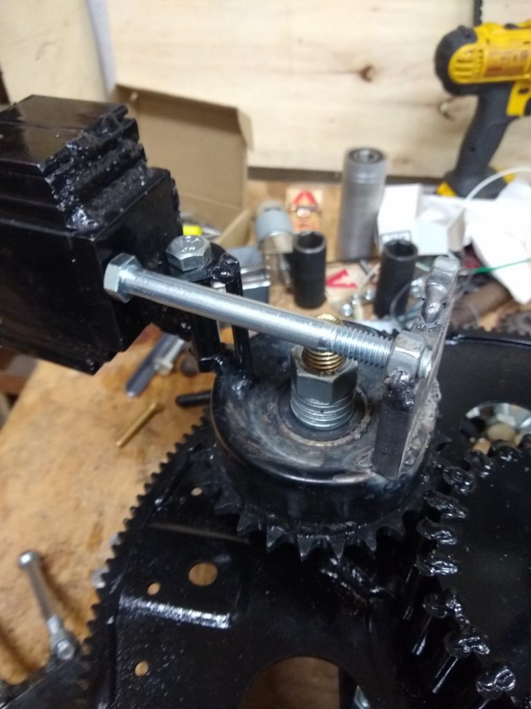
The PIE counterclockwise wheel (CCW) is nearly finished and will be tested very soon. I made a significant change to the “outer stop” which works so well to warrant changing up the model number to PIE 4.8 and I am installing them on all of the planet gears for the PIE 4.8.

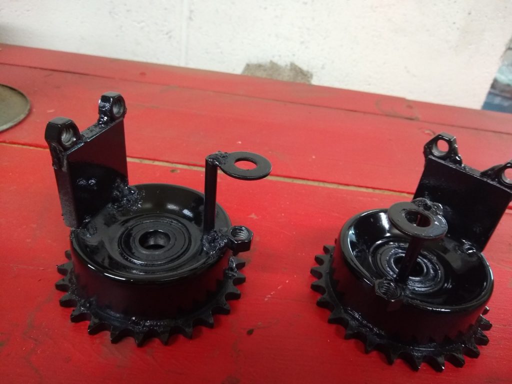
improved outer stops and “Halo” mounts after painting

Halo mount and improved outer stop as seen during setup

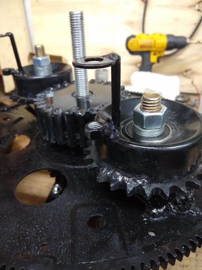
I have also improved the mounting (resembling a halo) for the swinging weight. This improvement also allows for the addition of strengthener braces if it is found to be necessary.

Halo Bracket for Swinging Weight

The new stops allow for actual adjustment of the stops. This will allow me to make small changes to stop position and find out if there is a particular “sweet spot” for the outer stop.

Improved outer stop and halo mount working well during SDC setup

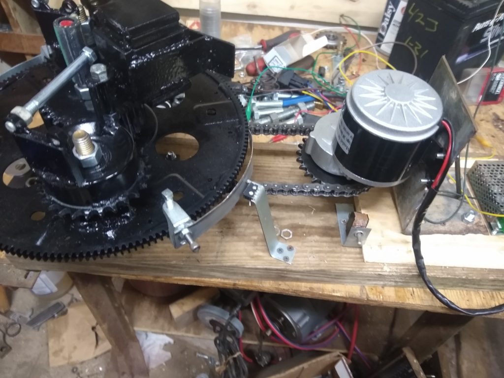
The CCW wheel is constructed to run on its own with its own separate motor and speed controller (as seen above). This is necessary to run the full gamut of necessary tests regarding phasing and RPMs. Once these tests are complete there will be better data regarding proper synchronization and whether the two opposing wheels should even be synched at all.

I have posted several videos on my YouTube and BitChute channels showing the building of the CCW and the new PIE 4.8 stops. Here (below) is the new PIE 4.8 CCW running its bench test with the SDC installed.

Here (below) is the first bench test run of the CCW before the SDC was installed.

Here (below) is the PIE 4.8 CCW set on some pipe rollers just to check for backward force (reversion) vs. forward force (thrust).

First Thrust bench Test of PIE 4.8 CCW Assembly