PIE 5.0 Update & “Scientific Heresy”

The PIE 5.0 does work! It is not as good as I was hoping, but it does show just one more way this “impossible” propulsion becomes possible! The things learned by actually putting hands to work in the shop far outweigh the mainstream physics falsehoods still perpetrated in many (or most) of our “higher learning” institutions.

What I am about to say is considered “heresy” in the “religion of science”:

Science is supposed to be available to everyone.

Science is supposed to be FUN.

Scientific information is supposed to be openly available and shareable.

Science and physics are supposed to be shared and debatable among all of us, not just the PhD’s. PhD’s who unfortunately tend to believe what they were taught in their final years of education, which is that their Graduate Degree somehow makes them “better” than everyone else. Science is not supposed to discriminate, science (by definition) is to “observe” with an open mind, not “dismiss” with no regard to the idea of actually learning what is possible.

That said, the PIE 5.0 did work, but just not as well as I hoped but that is actually a large part of what makes testing it successful! Every test, every build, every experiment, every failure, every debate & every argument lost has taught me something and makes me who I am today!

Latest Test of the PIE 5.0

The data and understanding gained from development of all of the PIE versions (including the PIE 5.0) is now being poured liberally back into the Trammel Engine project with a renewed enthusiasm! That alone is worth the time spent planning, laying out, building, and testing! And as a bonus, it is “fun“!

More to come soon, please check back here for updates!

PIE 5.0 Becoming a Reality & 1st Picture

So the first successful test of the PIE 5.0 concept is in the books! Although it is only a bench test with one “wheel”, built on the PIE 4’s frame, and sitting on roll pipes, there is no doubt that there is strong forward thrust with reversion at a level of “little to none”.

Adding more weight will definitely increase thrust as seen in experiments completed. An increase of RPM may also increase thrust, but that has not been experimentally confirmed.

So, what is the big deal with the PIE 5.0? No sun gear! No planetary gears! No impact zones! No stops to get broken!

What does this serve to accomplish? Less noise! Less potentially damaging pounding! Longer thrust pulse duration! No need for a pivot point to swing the weight! Virtually no reversion!

The one thing I struggle with is the need to make this work public while also wanting to build a business around it. Conventional thought says that it needs to remain secret, while every fiber of my being screams “make it public”. With guidance from above, I have built this, & with that same guidance will come the reveal.

Below is a photo of the first tested prototype. Much continues to change so more details will be added as work progresses.

Updated Website & Upcoming PIE 5.0

11/9/2022

It has been a long summer of trying to balance my time in my workshop/lab and my career as a Parts Associate, now promoted to Supervisor. Sometimes I think that I must be doing a good job, but there are some difficult days when I think that I am the supervisor because nobody else wants the headaches…

Trammel Update: The Trammel Engine has been rebuilt over and over and now 99% of the internal motion is now working as expected. There are internal components I call con-rods (connecting rods) which only pull and never push, then there are push-rods which can only push and cannot pull. The con-rods are now of a very strong design and their length is adjustable. We had multiple con-rod failures until this design was implemented.

The problem appears to be with the push rods. It was originally thought that their purpose was more of “timing” between the lower halves of the motor, so they would only need to basically “take up slack” with a spring load. This now appears to be incorrect. It seems that they must actually provide a “hard stop” which only pushes but cannot pull. Springs will still be used, but more as an ant- rattling device (I think).

The constant trial runs and failures precipitating rebuilds and repairs have really taken their toll on me mentally… I need a freakin’ win for crying out loud! So I am now (on an opposite workbench) building a PIE 5.0! It is a culmination of PIE and Trammel knowledge gained over the last 3 years and preliminary tests are incredibly promising.

It is still an ugly “Frankenstein” of a machine, but I will post pictures as it becomes something to look at! The good news is that even though it is still in the earliest stage of development it is already making pounds of thrust (too bad NASA)! With one wheel! With one weight!

Sorry I don’t have pics yet of the PIE 5.0…

Our web site (http://stclairtech.tech) is revamped and rebuilt with new fresh graphics and a much nicer interface which is easy to navigate. I also have a page showing some pictures of UAPs (UFOs) over the St. Lawrence River on the US & Canadian border. The pics show black, odd-shaped objects in the air which might be explained away as birds or insects, but they are 100% real photos of objects which only show up on the digital camera! These are completely invisible to the naked eye! See these photos here: http://stclairtech.tech/UAPs/

Thanks for reading and following along… Talk to you again soon!

The Origins of the Trammel Engine and Recent Activity Update:

4/17/2022

Happy Easter!

Although work has slowed a bit progress continues, and here is a synopsis of recent activity:

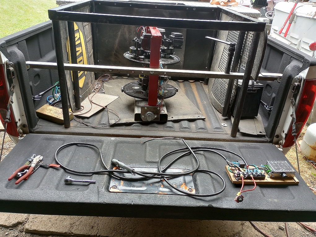
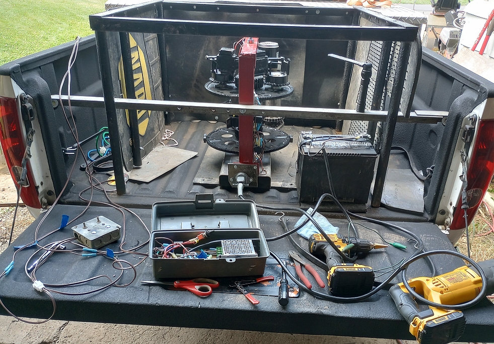
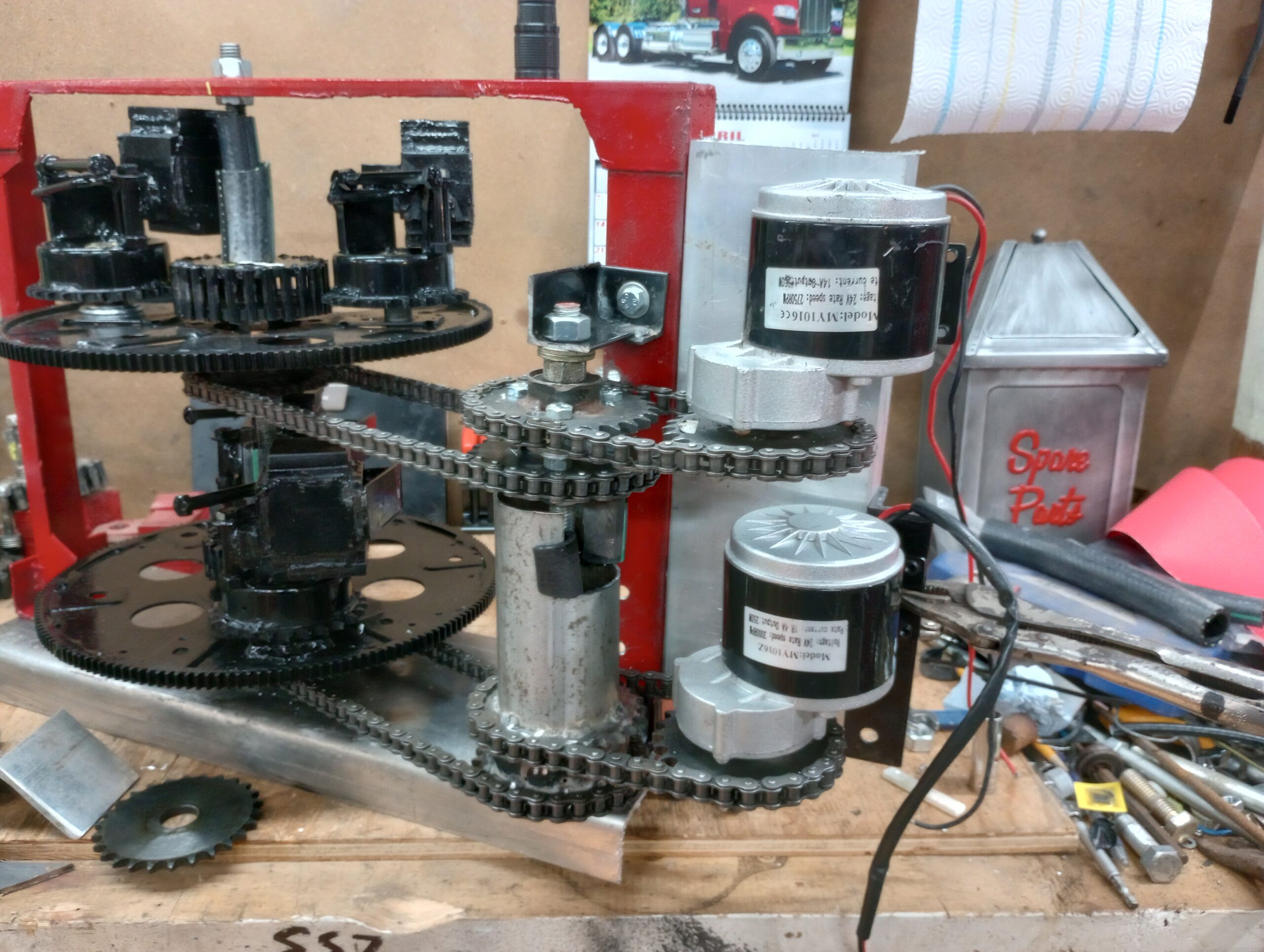
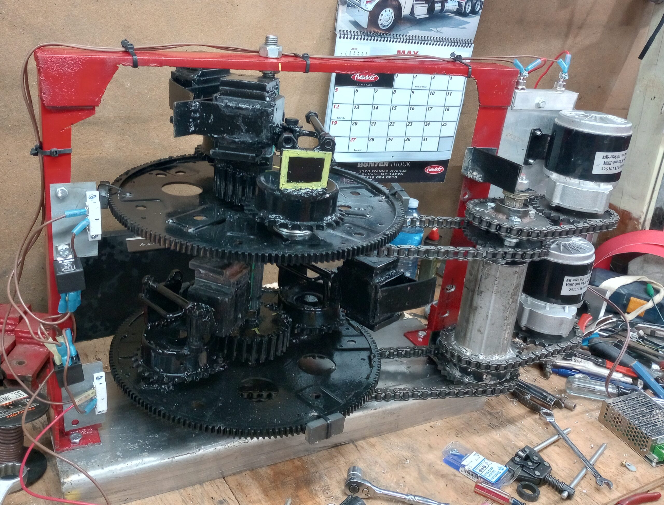
1- The Trammel engine got a new (more powerful) motor with speed controller.

2- Trammel displayed thrust only during acceleration with new motor.

2- LOLA or Linear Oscillation Linear Thrust experiments began.

3- Linear component analysis showed it is useless without proper energy storage and release.

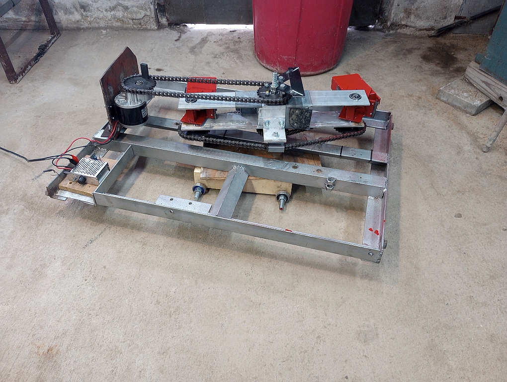
4- LOLA v.1 is a linear drive experiment where dual linear components rotate parallel with the axle.

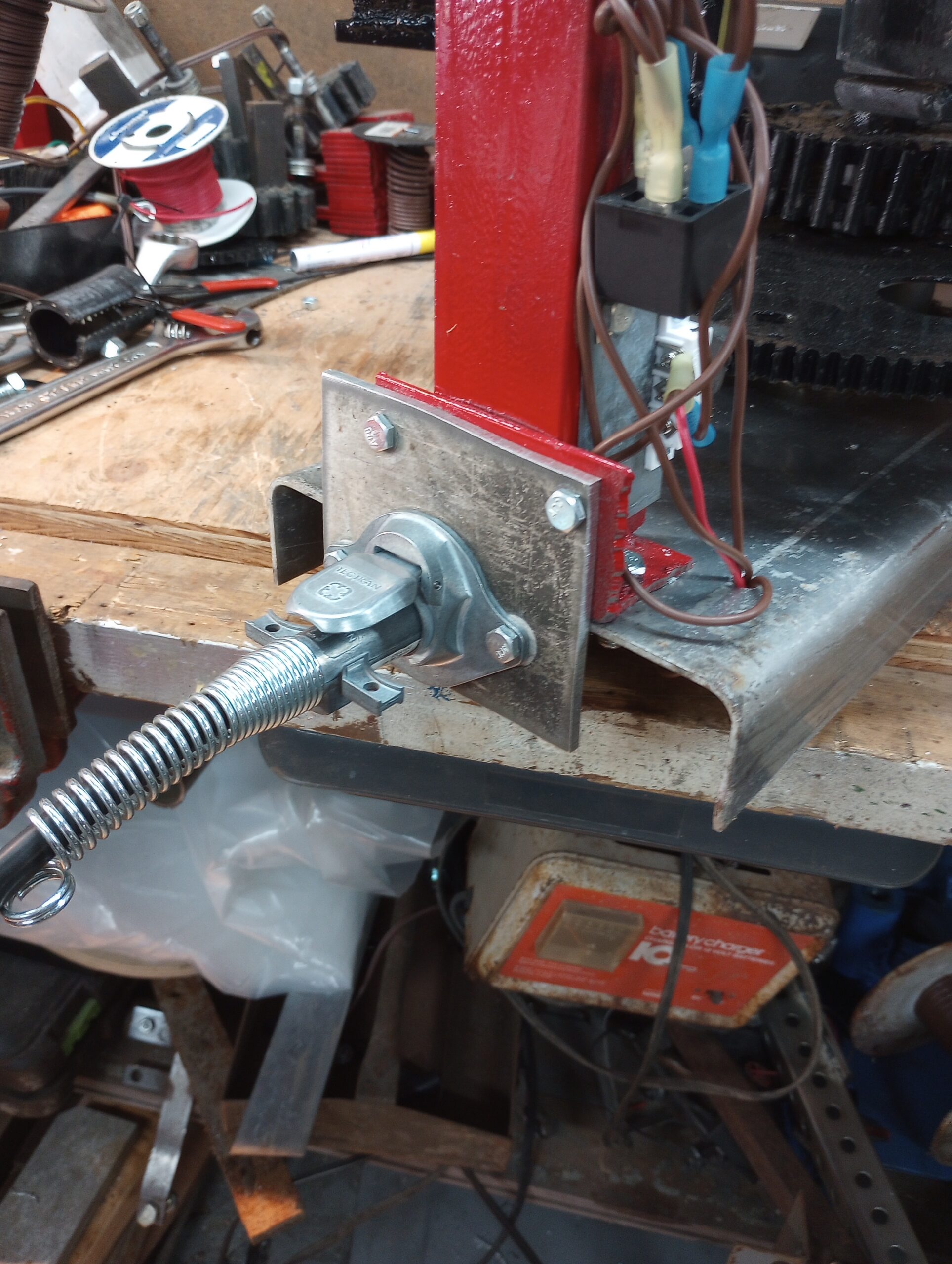
5- LOLA v.2 is a linear drive experiment where a single linear component oscillates which also builds and releases energy by building spring tension and releasing it as the mechanism rotates “over center”.

6- Both LOLA experiments allowed some better understanding of the movement of energy between the mechanism and “etheric inertia” which creates propulsion.

7- The term “etheric inertia” was coined by me. It is the inertia which is not part of the machinery itself, but instead is the inertia which is manipulated and is observed as the movement of the drive and is usually expressed with terminology such as “inertial thrust”. Where thrust would be the verb and/or adverb, “etheric inertia” or EI would be the noun and/or pronoun defining the “environmental force” not just the action of that environmental force.

Note: Inertial Doppler was also coined by me as the observable increase in thrust which happens as the vehicle using the inertial thrust engines move faster, mimicking a type of Doppler effect.

8- During recent APEC conferences which included presentations by Ross Small, myself, and others, it has been mentioned that the RBI machine of Ross’ an my PIE X/Trammel Engine are derived from the work of Mike Marsden who was the inventor of the Mac-Quan. Mr. Marsden dropped out of sight before the unveiling of his second-generation Mac-Quan which was set to occur at the annual Wright brother’s celebration in Kitty Hawk, NC around 2011 or 2012. The Mac-Quan has long been the “gold standard” that all inertial propulsion developers have hoped to duplicate. Mr. Marsden was rumored to have passed away, but I believe he has retired and is now living in relative seclusion somewhere in North America, no longer having anything to do with the technology. The reason(s) is/are up for speculation as he never actually said why he closed up all of his businesses in Texas and dropped out of sight. Even his old web site (www.earthport1.net) is missing from resources such as the Wayback Machine.

I have been fortunate enough to have made the acquaintance of some people who knew Mike Marsden firsthand. Although he did not “give away” the full secret of the internal mechanisms, he did guide these people toward the correct answers. Their information and engineering skills combined with my mechanical background and “get it done” work ethic has produced the PIE X or Trammel Engine as I like to call it.

I have agreed to not divulge the inner workings publicly in return for the engineering data. Hopefully in time the design will be perfected and surpassed at which point it will be part of textbooks around the world.

If anyone here has ever been in contact with Mike Marsden, knows anyone who has been in contact with him, or knows anything about this technology, I would love to hear from you. I will gladly keep any information anonymous and secure and not share anything without your express approval. Email me at stclairtech@stclairtech.tech.

Notation:

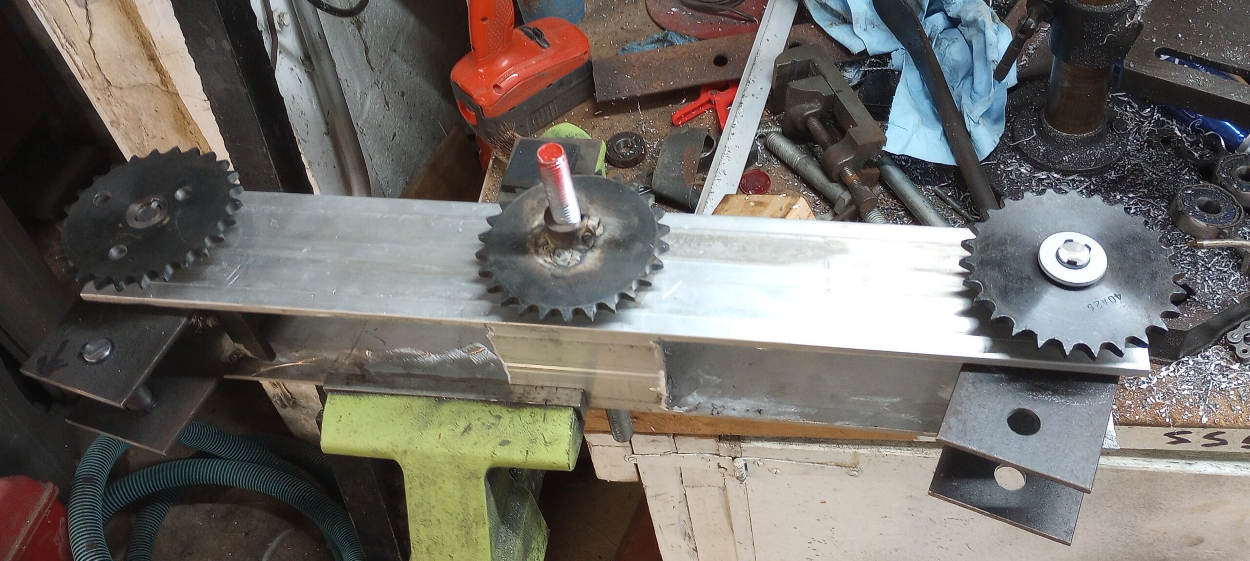
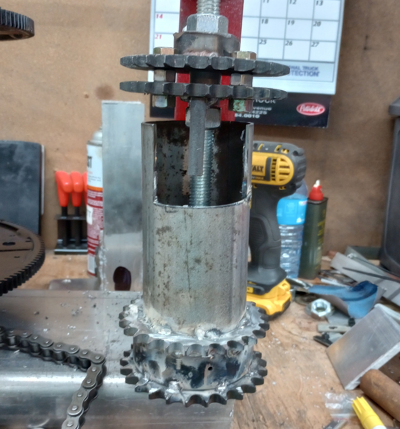
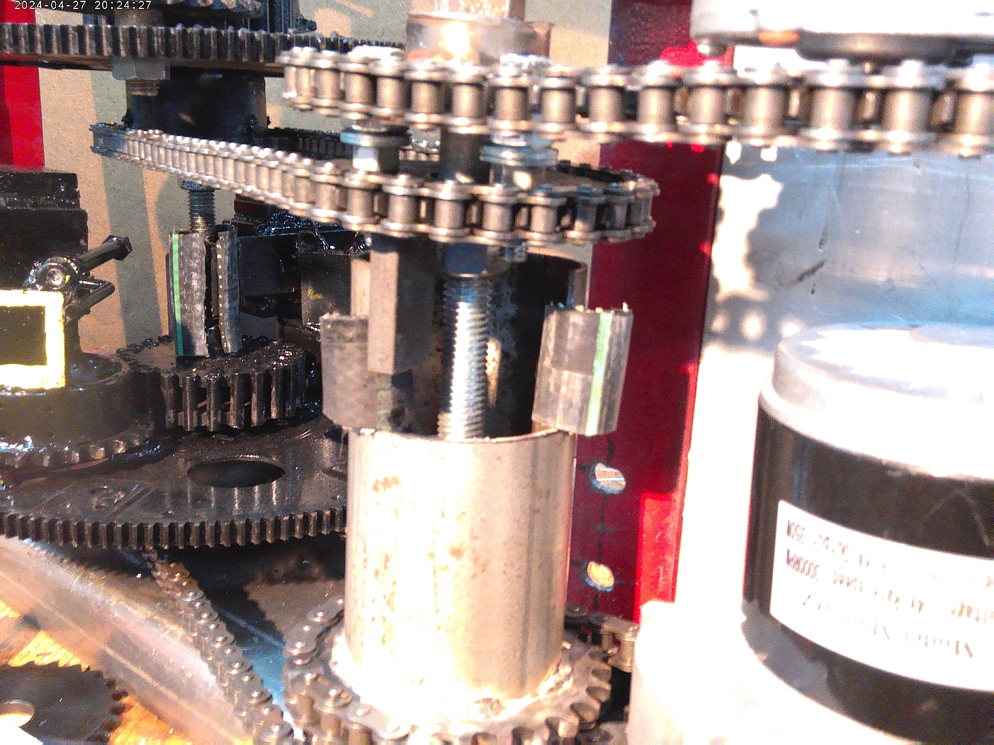
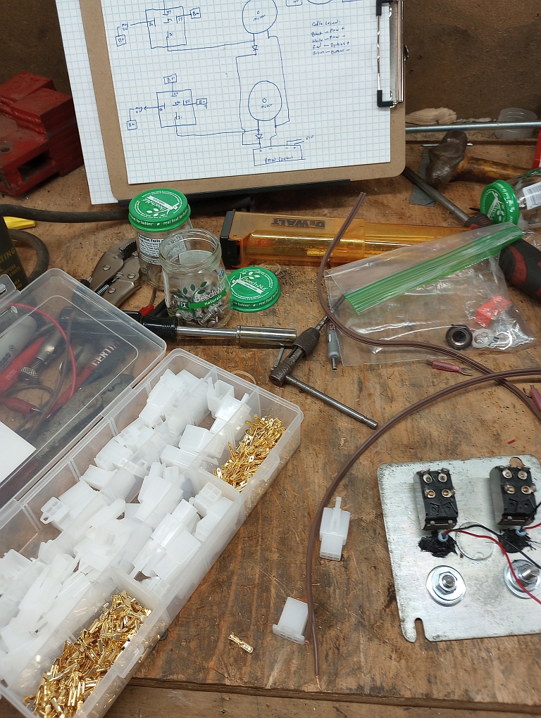
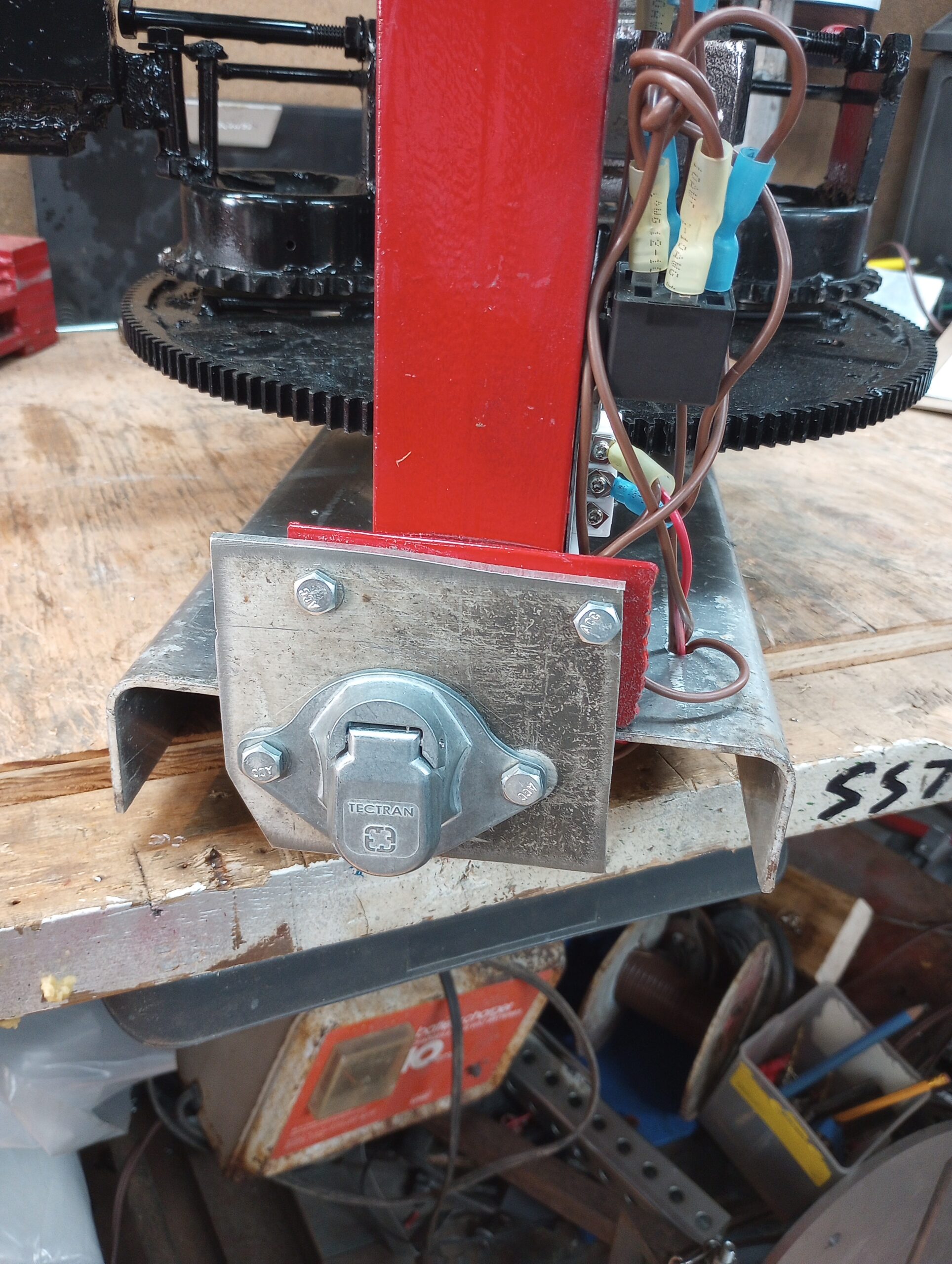
Testing rotation speed with a sensor and lab scope setup is now showing that the assembly built to eliminate backfire is keeping the internal speed change reaction times to be too slow to provide proper output thrust. Internal components will now be modified, probably using a pair of timing chains instead of cam-like lever assemblies.

Personal note: I truly long for the day where this is fully functional, and we can have open discussions regarding the design and inner workings of the Trammel Engine. Maybe I should be creating a Power Point presentation as I go…

Trammel Testing, APEC, PIE Mini

It has been MONTHS since I updated here… A lot has happened in my life and in the shop! For those interested, I have switched gears in my professional life. Since the change is quite dramatic, I have been under some stress “getting in the groove”, but it is a needed change and I’m getting it all figured out.

The PIE X aka Trammel Engine is coming along. Inside it (still not ready to reveal too many details) are some components which were made too weak, but they have been rebuilt and replaced with much more robust pieces! I have experienced some intermittent thrust and have kept moving forward with this as much as possible. I also recently received a much-improved motor and speed controller which is now installed.

A Look at the New Motor
First Run Test

It has become quite evident that as I contact potential business partners and investors, I need a small and lightweight demonstration model which can be taken along to those meetings. With that in mind, I introduce the “PIE Mini”. The PIE Mini is a nearly complete, single weight, working, demo model which is really small and light with plastic gears and a hollow tube instead of a large “wheel”. It’s power source is a super cheap cordless screwdriver from Harbor Freight. Although it is intended to be a portable demonstration device.

I believe it will also be a design which could become the first model of a sellable working model for science minded people everywhere to experiment with.

There are a couple of videos of the PIE Mini on BitChute .

First Test on Wheels

I have also now run a live demo of the Mini at the APEC conference on Feb. 27, 2022. During this presentation I showed that the unit actually needs mass to operate and that is really it’s only environmental prerequisite. I should be posting that presentation on my BitChute and YouTube channels very soon. Until then, here is a link to it on the American Antigravity YouTube channel.

Part 1
Part 2

I want to thank Ross Small for joining the video conference with a presentation of his own. He is building a “linear thrust” machine in the hopes that it will be a helpful learning aid for everyone to better understand the mechanism of inertial propulsion. Some of those very principals are integral to the Trammel Engine, and have also got me thinking about other, future, design builds.

Ross Small’s Presentation Part 1
Ross Small’s Presentation Part 2

PIE X Being Built Now

I am still around! I am still building! I am not going anywhere!

It has been quite a while since my last posting and my last video. I have been hard at work on the PIE X design. I am still not at liberty to detail its design except to say it is based on a series of rotating discs which use specialized components under tension and using a “Mass Displacement” system should create efficient linear thrust. It is still being called a PIE because it does have a pulsed propulsion component, but these pulses “should” happen 4 times per revolution and run at 1000 RPMs or more so the pulsing should be MUCH smoother than that of the previous PIEs.

Although this is not my original design, and it has been done before, there are no working devices known to exist and its duplication attempts have all been in vain… Until now. Well, soon anyway! The main unit is framed up and the rotating discs do rotate very well. The specialized internals are partially complete, and testing has had some very positive results thus far!

Without giving details regarding the origin of this base design, the person who originated it stated that they ‘…will not give away all my secrets…” and emphatically stated that others will have to “…figure it out for themselves…” and so we are figuring it out now.

It is unfortunate that the original designer was (and still is) compelled to distance themselves from this technology!

What I can say about the PIE X is that it is using 3 rotating “wheels” which are referred to as “discs” or “plates” and has at least 10 times more parts as the PIE 4.x series has in it, not including nuts and bolts holding the framework together. I can also say that I have built it with absolutely no regard for overall weight. Most of the unit is built with heavy steel components rather than lighter weight aluminum and/or hollow parts. Overall weight has become too much to easily move around as it is well over 130 lbs. and still does not have an electric motor installed. I am hoping that with all the excess mass it has enough thrust to easily demonstrate linear thrust.

Right now I am turning it with a hand crank, and because of a problem with what I refer to as a “backfire” I will not be installing a motor until later. The backfire is 100% mechanical (no actual fire) and refers to a point internally where stresses are suddenly released in the wrong direction and a backward movement happens (inside). This could have catastrophic effects, so the issue needs resolution before a motor can be used!

I did post a rather ambiguous video online with the internal pieces covered (for now)…

First Public Look at the PIE X

PIE 4.8 Re-Phased and then Switching to Co-Rotating Design Testing (2 Updates)

On 7/31/2021 the counter rotating PIE 4.8 was re-phased to have the planet gears synchronized (self-propulsion mode) but then one plant gear was removed from each wheel so that forward pulses will alternate from on side to the other. The non-functioning weights were fastened to the planet gear mounting holes to help balance the wheels a bit.

Results were very similar to having all the planet gears and weights in place and operational with road testing showing a 4% to 6% reduction of engine load at the standard speed of 55 MPH with little to no headwind.

I believe this poor performance may be due to the counter-rotating wheels. Previous testing has shown better thrust using co-rotational wheels (rotating in the same direction). It has been suggested that counter rotation might be needed for stability, especially in either an air or space (aerospace) vehicle, but co-rotation should be very possible with proper management using either air foils or gyroscopes. Co-rotation should still be quite manageable a with minimum amount of manipulation.

8/10/2021 Update

I have now rerouted the chain on the PIE 4.8 so now the Left and Right wheels both turn clockwise, and I have modified the ramp on one of the RH wheel’s weights for the direction change and timed the wheels for self-propulsion (synchronized). With just one weight on the right wheel and two weights on the left wheel I now see that it is a definite improvement over the counter rotating wheel setup!

The first noticeable difference between counter rotating and co-rotating is when counter rotating in this same configuration of 2 weights on left and one on the right the propulsion pulse was strong when a single weight pulsed and weak when two weights synchronously pulsed. With co-rotating wheels the propulsion pulse is strong when a single weight pulsed and doubles in strength when two weights pulse synchronously. In simple terms, the unit is stronger when co-rotational!

I need to put trolley wheels under it again to test properly on the bench, but the unit seems strong and is pulling itself (sliding forward) across the bench when running even without fine tuning the gear timing. Next, I will adjust the gear timing and modify the other weight for clockwise rotation so that I can complete this round of testing.

If there was lots of extra time to do extensive testing it would be best to build it with 4 wheels, two co-rotating and two countering them to be able to arrange them in different ways to record and study the results. I don’t feel it is necessary at this time as the testing I have done is more than adequate to demonstrate the workability of the PIE system.

I have discussed the origin of the SDC and the subsequent positive effects of its use, and when I was setting up the PIE 4.8 to co-rotate, I could visually see the point of heavier motor load in the PIE’s rotation. So I published a short video of this visually obvious effect demonstrating the position in rotation which needs the RPM boost using the Speed Differential Control (below).

More to come soon!!!

PIE 4.8 Changes to SDC and Issues on Latest Test Drive

New SDC Switch

It has been a very busy several weeks since I have had opportunity to update this blog. Work and life have been very busy and work on the PIE has been slow.

The re-phased PIE 4.8 has had the first road test completed with no SDC as the SDC micro switch is a continuous source of problems. The lever on the switch tends to break or get bent very easily and the roller wheel also tends to fall off frequently, so it was decided to use a “proximity switch” as a non-contact alternative. The switch chosen is a magnetic switch used for building security systems as a door/window open/close sensor. This is easily activated by mounting magnets instead of mechanical actuators and this works very well.

The PIE 4.8 second test drive was, however, less than outstanding. The re-phased PIE wheels and SDC “should” have yielded much better results than the previously phased tests when it was set up for “self-propulsion”, but the results were very disappointing as the engine load reduction was only in the 4% to 6% range.

I believe it has to do with the counter rotation of the wheels. The “zone of thrust” or “thrust zone” on a single wheel is rather wide as it pulls forward through a good 45 degrees of the rotation, by having the counter rotating wheel, the “thrust zone” is effectively narrowed but instead of “focusing” thrust, it only eliminates part of it.

The next steps to calculate the reason for such failure will be to adjust phasing back to synchronous and increase pulse torque by removing one weight from each wheel. The thrust will alternate between the CW and the CCW wheel, this should demonstrate the theory of the wide thrust angle vs. narrowing the zone.

Phased Back and Switched Down to Two Planet Gears

The non-functioning weight is being used as a balance weight. The planet gear that is not being used is removed and the weight is bolted to the wheel in its place which balances the wheels enough to keep it from tearing itself apart.

One Planet Gear Removed and the Weight Used for Balancing Wheel

If this works out, the plan is to reverse the rotation of one of the wheels and repeating tests with co-rotating wheels to increase thrust without narrowing the “thrust zone”.

Ready For Road Test Set #4

On a side note, I believe the thrust zone will automatically be much more condensed (thus stronger) with a different design. Perhaps the PIE X will accomplish this.

PIE 4.8 Testing- and -Doubters, Debunkers, and Haters:

Well now, it seems that with the openness of the experimentation, building, fabricating, and functional videos that the “it doesn’t work” folks have become “it only works because of” folks.

The better we get this working, and the more verified data there is, the more people keep coming up with reasons they think we get propulsion. Primarily this presumptive opinion input has revolved around friction. The common theory is that “contact” with virtually anything is the friction causing propulsion. I cannot say that anything is impossible, but short of tossing this thing out into space it will be nearly impossible to “disprove” that theory! Here is my position on this… “Who freaking cares?!?!?!” It just works, so let us expand on this and put it to use for the betterment of EVERYONE!

I get it that the super smart technical theorists believe that anything that isn’t incredibly complex simply cannot work. Sorry people, but that is just another false theory which has been mistaken as fact.

Mine is NOT the only system that works, mine is not the only tech that needs to be openly replicated. If the replications are done with an expectation of failure, it will most likely fail. If they are done with an open & optimistic attitude with an expectation of recording valuable data, extraordinary things are possible!

PIE 4.8 First Test Setup

I have recently published the video on YouTube and BitChute of the first round of Dual-Wheeled testing with fully independent asynchronous control of each wheel (CW & CCW rotating). More testing videos will be published, and a comprehensive report will be published when these tests are complete. That video is visible below.

PIE 4.7 and “PIE X”

PIETECH 4.7 and “PIE X”:

It has been a while since my last post, or video so here is an update:

The PIE 4.7 second half (CCW wheel) is progressing, although somewhat slower than I would prefer as life’s circumstances have presented certain obstacles to its advancement. The first “dead blow” weight for it is ready to install, and another is in process.

I always said it is not a good idea to have more than one project going at a time, yet that is exactly what I am doing…

After communicating at length with other builders, I have split my time between the PIE 4.7 and a new design, the “PIE X”. It has some radically different internal components and will look a bit different but it is still what I would call a Pulsed Inertial Engine, so right now it is known as the “PIE X”.

This design has originated from other people so I will need their permission to “open source” any of that information! I require their permission to share or publish the information leading up to the PIE X without the consent of those who have been kind enough to share the basic design information with me!

If the PIE X is as feasible as predicted and becomes something worth pursuing more information may be provided (with permission), and if it falls short, I will provide thoughts regarding that failure (still, with permission only).

Note: The PIE X is quite a bit more expensive and much more complex to build and fabricate the components for, so it may not be something the casual hobbyist would feel comfortable with, at least not until there is a working prototype to prove the principals.

Those who know me and those who have followed along with my PIE/PIETECH projects know that I do not randomly spout “theory”. I only present factual information so until I have an experimental prototype, I would not request permission to elaborate any technical information. I only mention the PIE X as an ongoing project because it does slow the PIE 4.7 project and has pushed back the timetable to begin full testing. I am hoping to be performing “on road” testing of the PIE 4.7 by early June which gives me about 8 weeks.

I hope to be posting photos and videos VERY soon, so right now I need to go get busy, I have a PIE 4.7 to finish building and a PIE X to get underway!