8/11/2024
Quantified Backlash Drive:
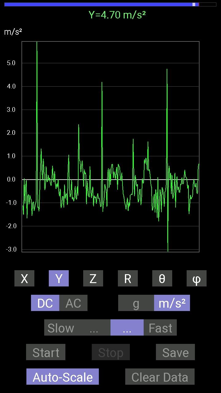
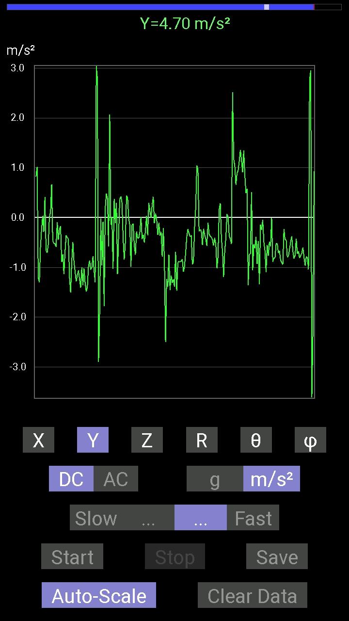
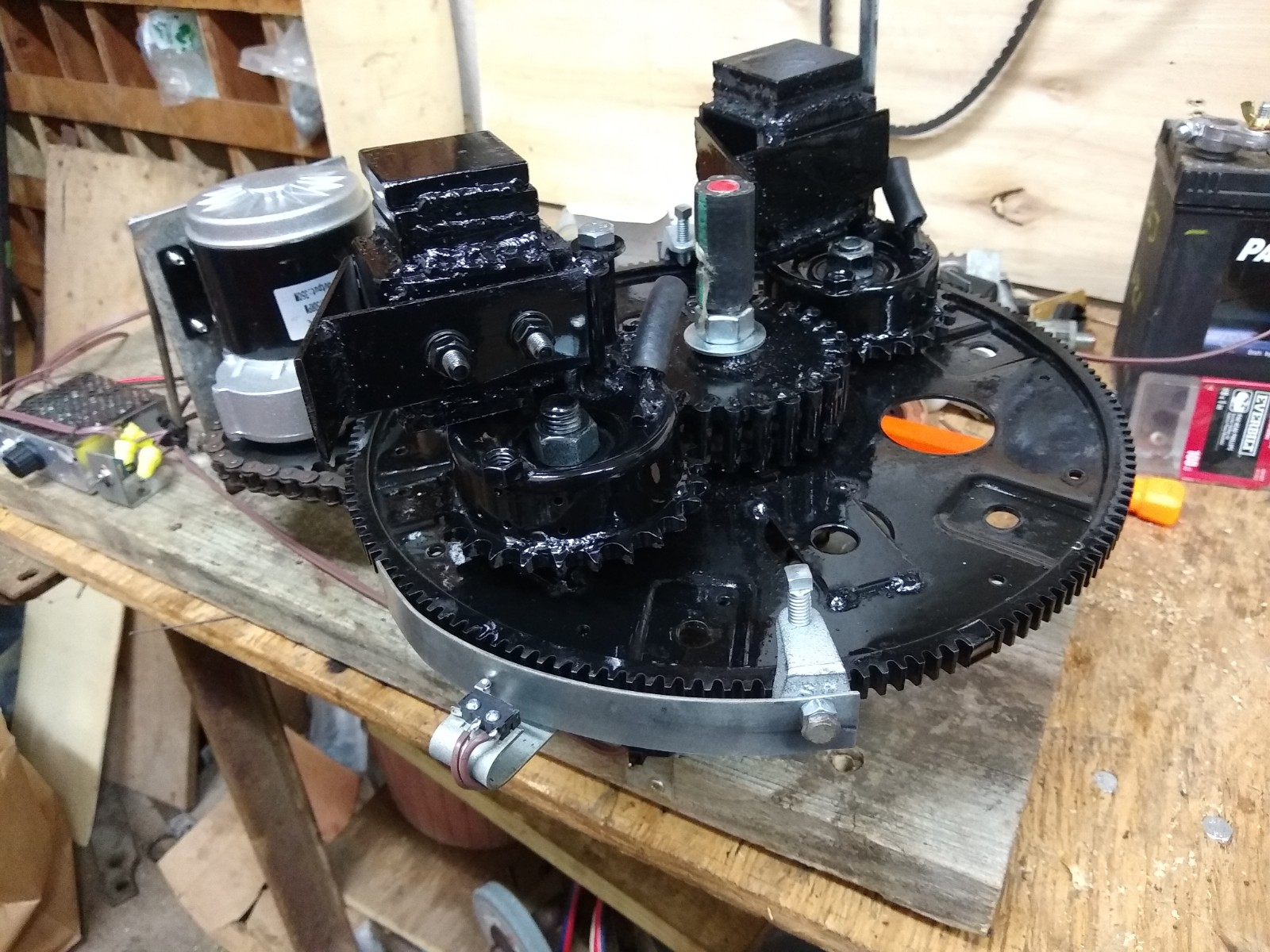
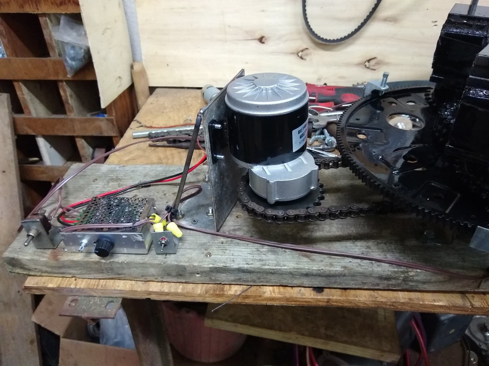
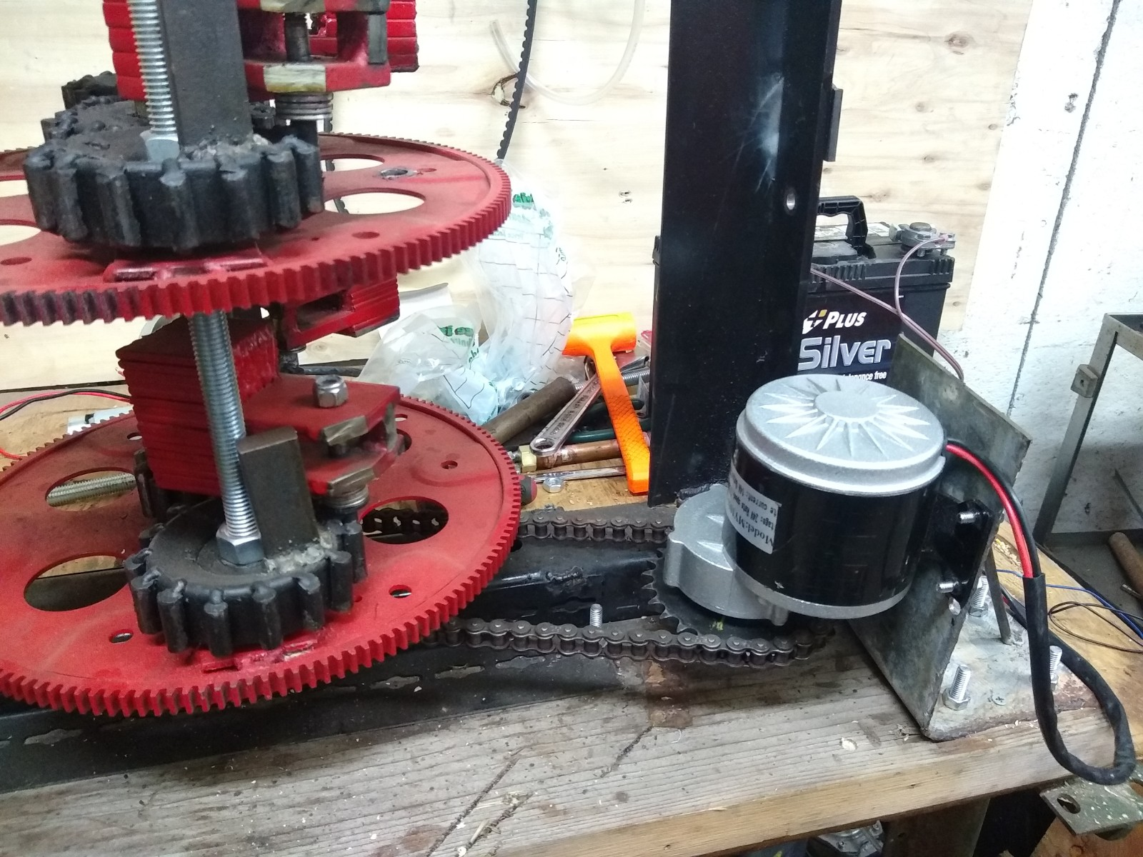
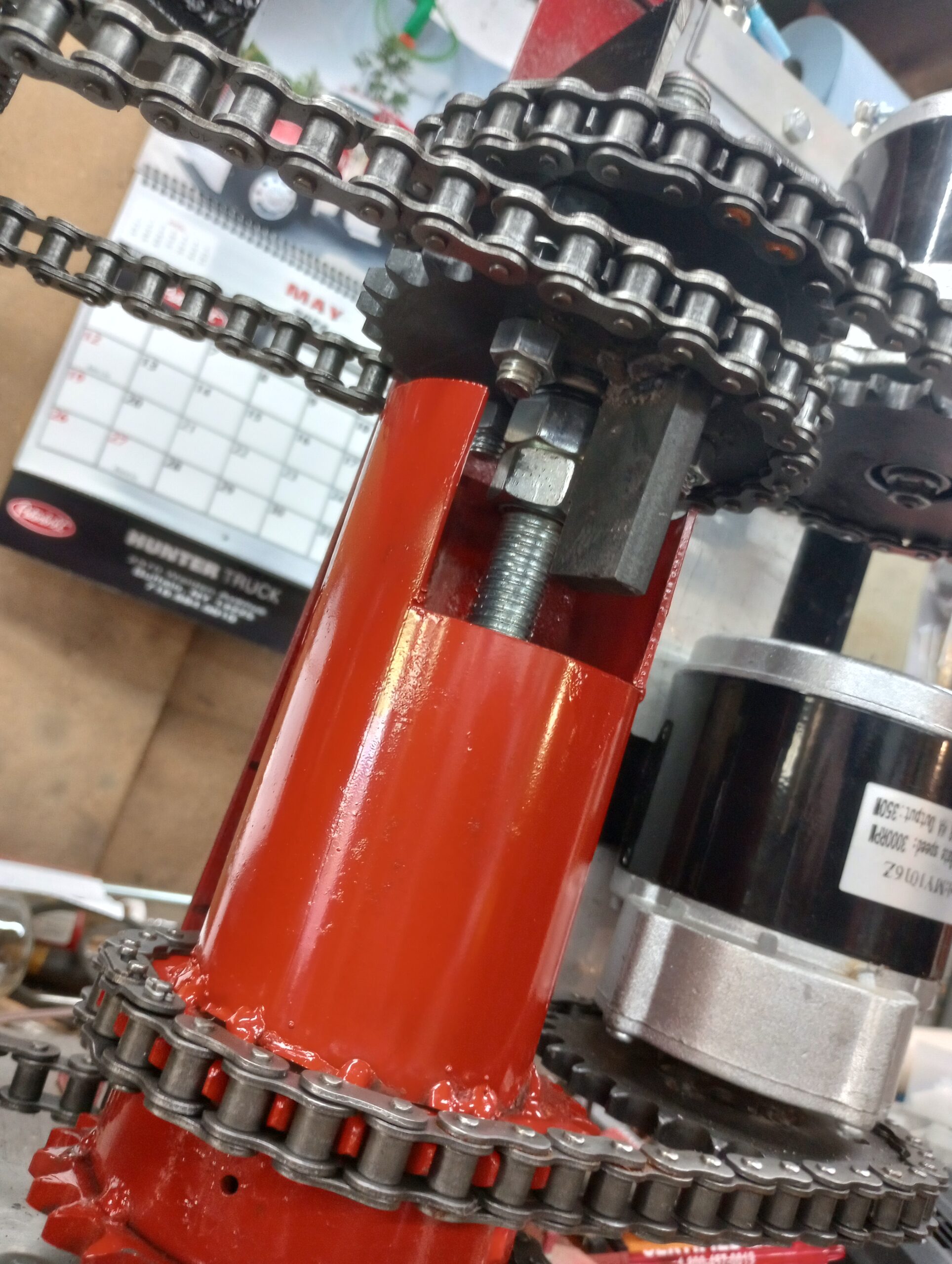
We have been testing the Quantified Backlash Drive (QBD) coupler for over a month now. Running the PIE 6.0 with 2 motors and the QBD keeping the synchronization within the working spec has resulted in a PIE that has minimal vibration, near constant thrust, reduced noise, low power usage, and excellent performance.
Actual thrust has not been measured, since this has been about the QBD design. The PIE 6.0 uses the rotating assemblies from the PIE 4 machine so thrust was never expected to exceed that of the PIE 4.
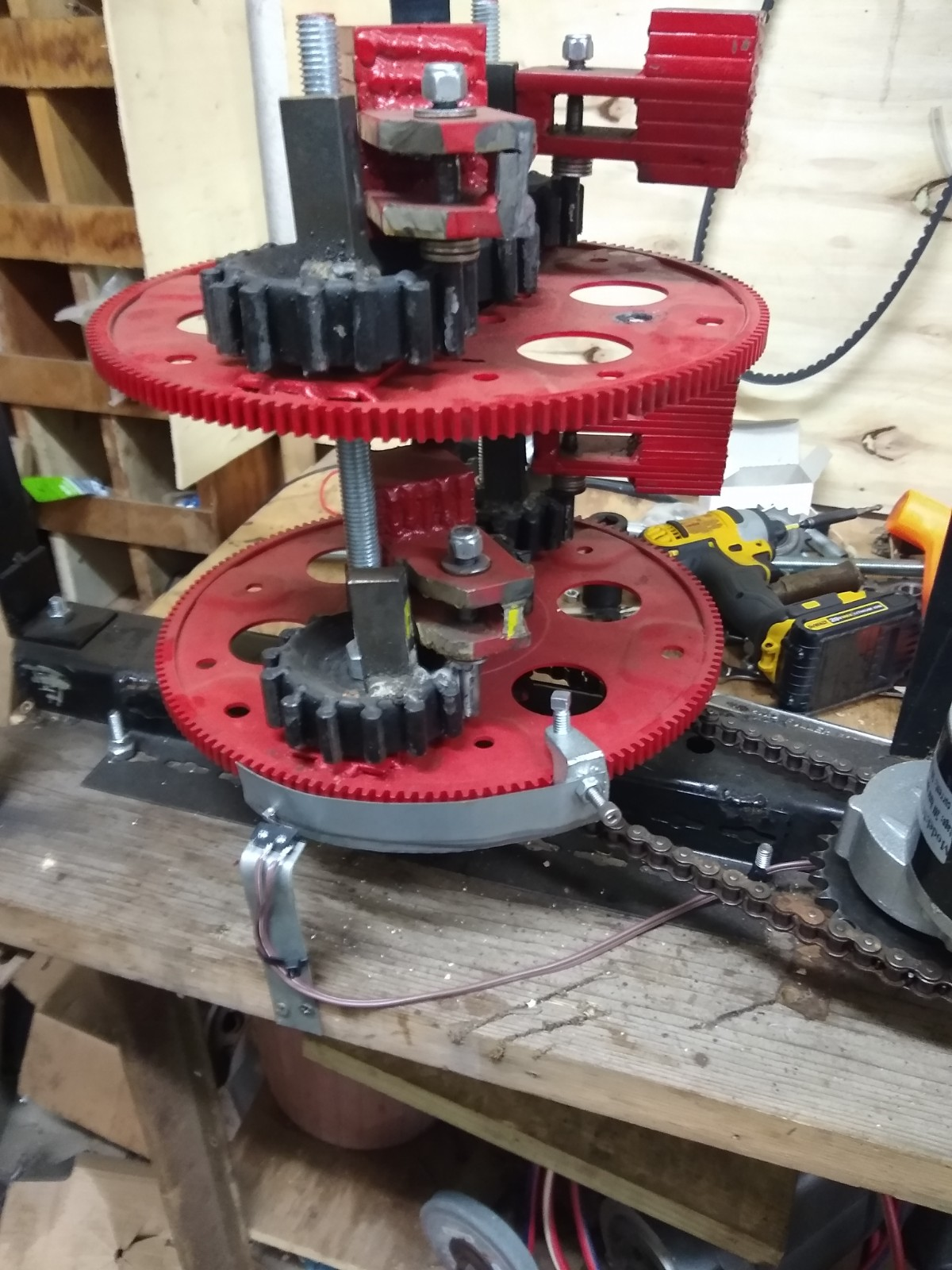
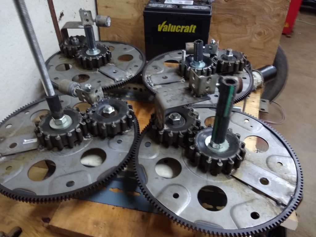
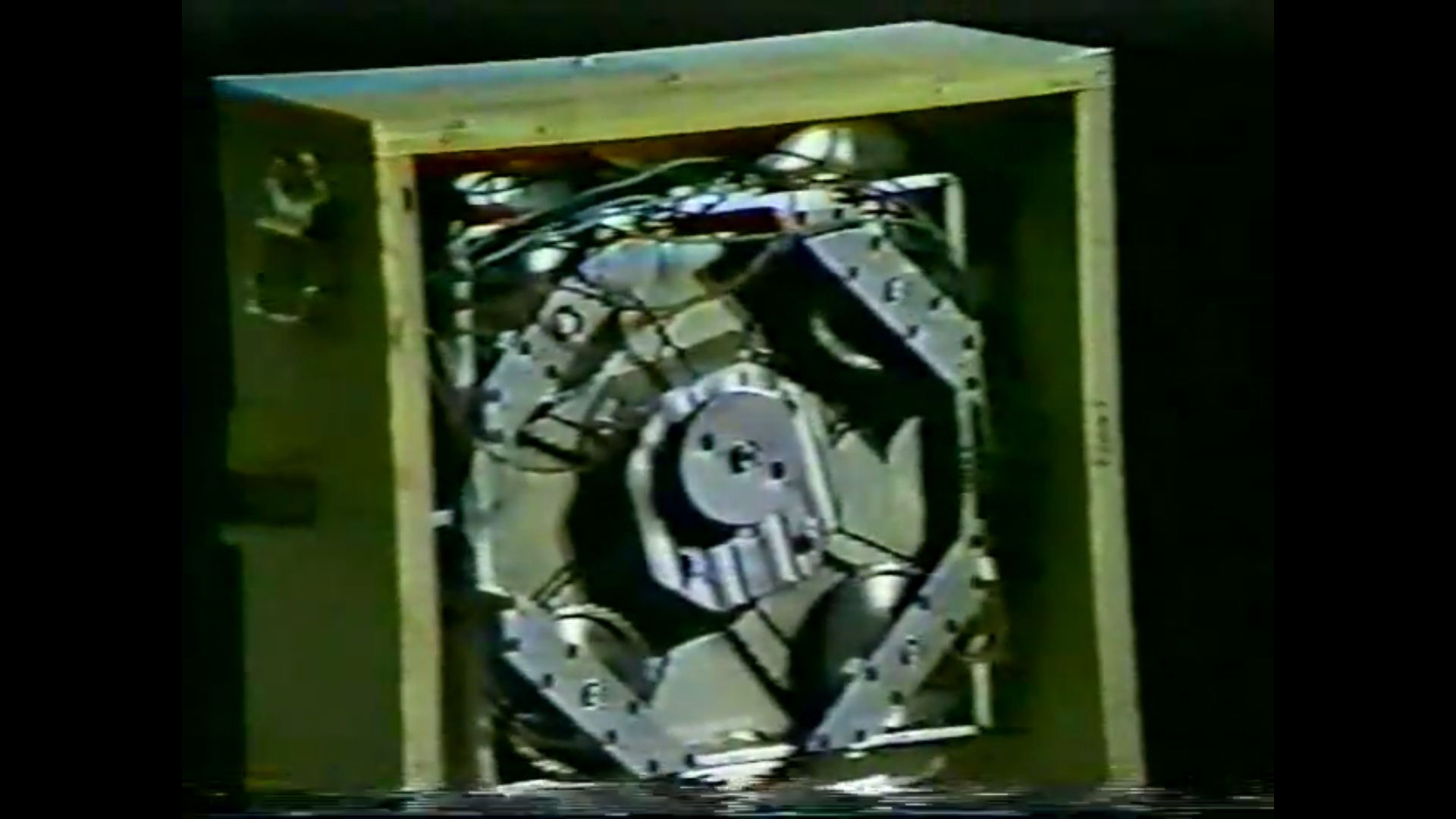
Thinking about the video presentation with Roy Thornson presenting his last design which was intended to go in an airplane to assist propulsion and even be the primary propulsive force eventually, we can see exactly why it never made it “off the ground”. In the video and in the very few photos available we can see there are 4 rotating wheels connected by roller chain, or timing belt, to a central motor drive hub.
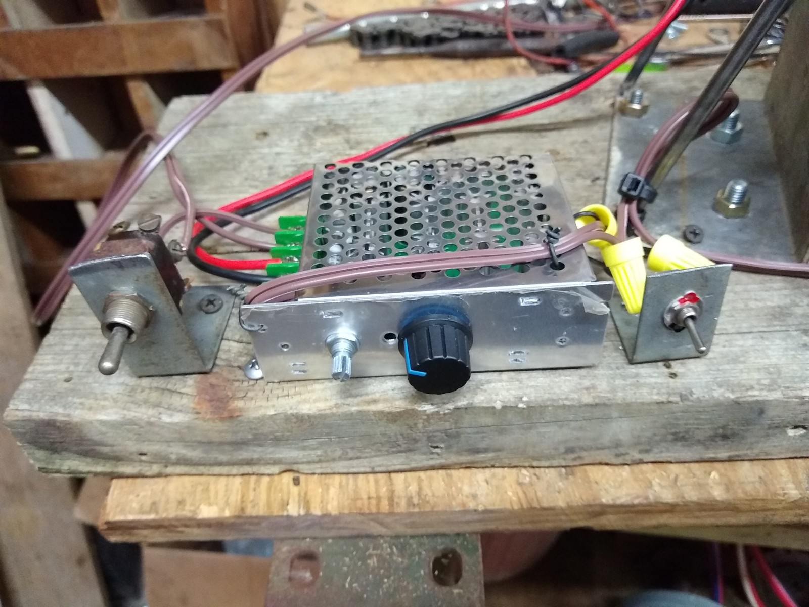
Along with several other things that Roy never got figured out (to the best of our knowledge), Roy was unaware of the negative effect of reducing speed in the range of 90 degrees before the mass reaches “apex”. We reach this supposition because he did not use any kind of Speed Differential Control (SDC) system, so the rotating speed (RPM) input was constant. However, if there was a load introduced to the motor as it entered the 90-degree range it would be reasonable to think that the motor’s RPM might have dipped slightly. Even dropping a few rpm (example 150 down to 145) during that phase would be enough to cancel most of the propulsion!
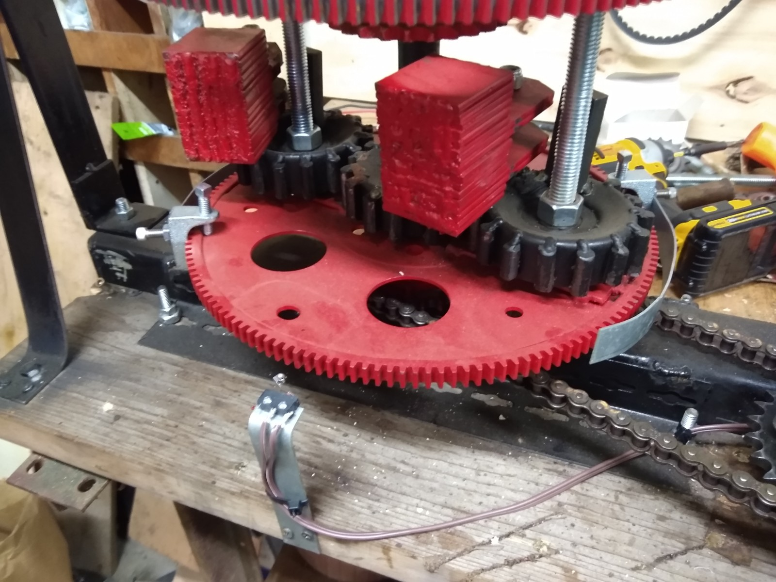
IF Roy had timed the wheels all the same and used only 1 mass (weight) per wheel, it would work. He could have even spread it out amongst the wheels a bit to allow each to come to apex within a 20 to 30 degree range and still had some propulsion, but the only way to get that design to work is with a separate motor for each wheel, or pair of wheels, to attain a maximum of 4 pulses per revolution, AND, keep them synchronized (timed) with a QBD.
This said, it would now be possible to build a replica of his engine that, with the proper modifications, would actually work! — Any Takers? —