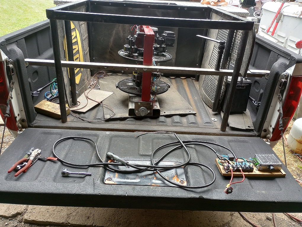
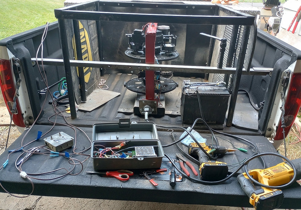
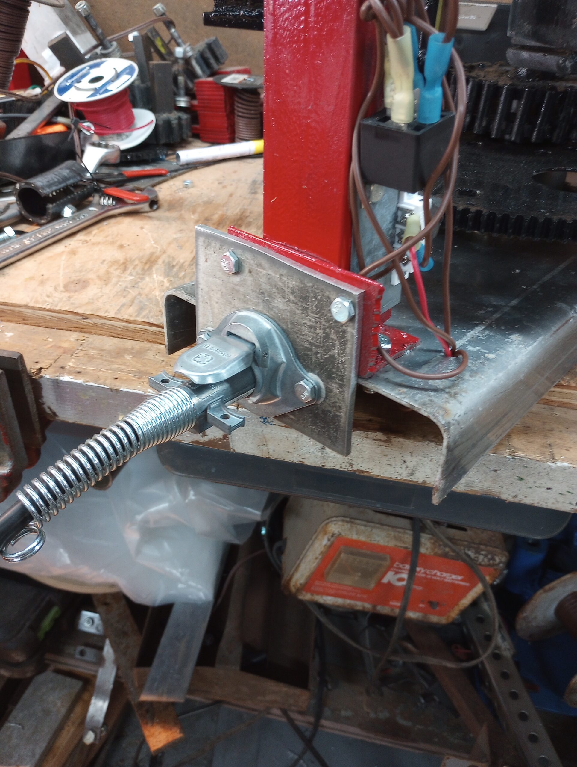
A few weeks ago (June 16, 2024), the PIE 6.0 was mounted in the test vehicle. A protective & sound deadening box made from steel tubing, plywood and several thick rubber mud flaps was built to cover it. Due to personal time constraints, it wasn’t run & tested until nearly 3 weeks later…
July 6, 2024: The PIE 6.0 has successfully completed its maiden voyage! The PIE design is solid so there are really no surprises there. This test was mostly about the Quantified Backlash Drive.
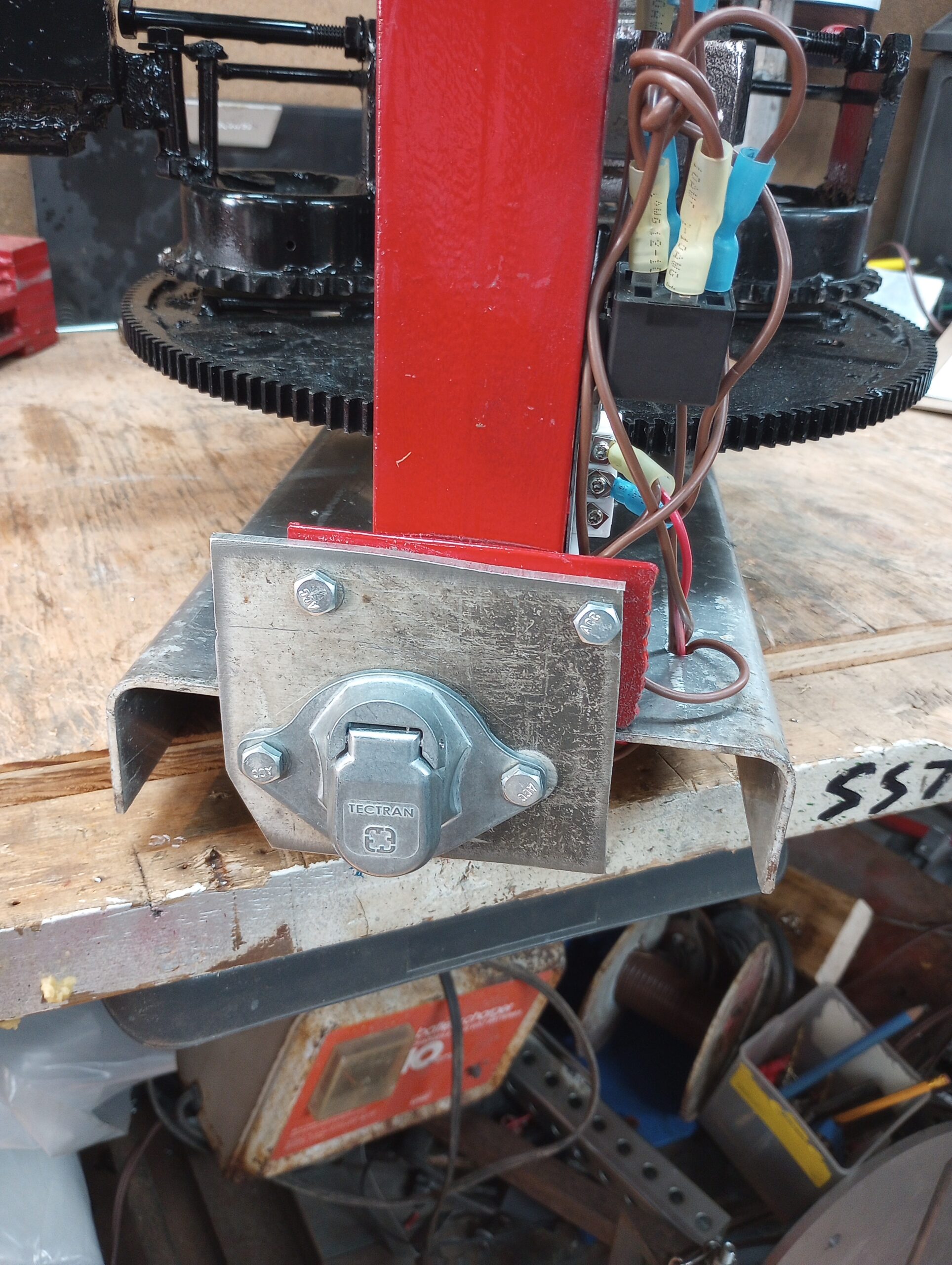
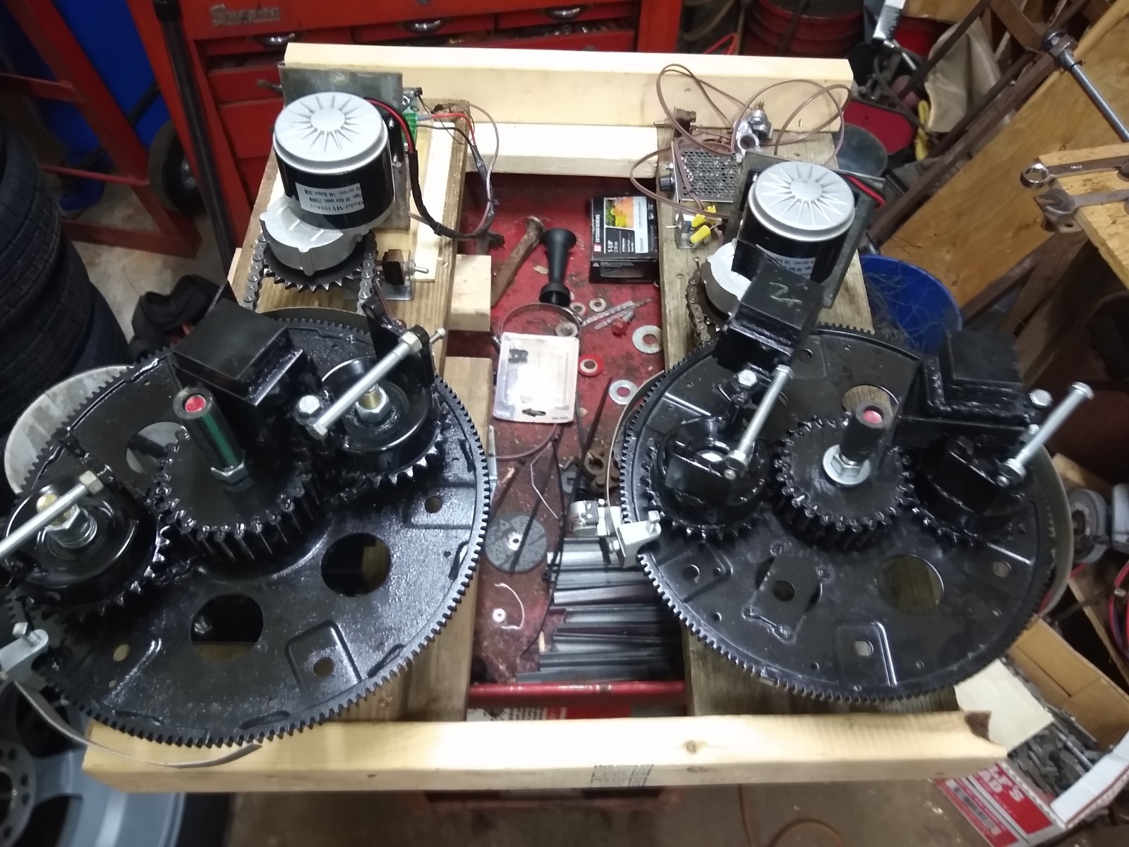
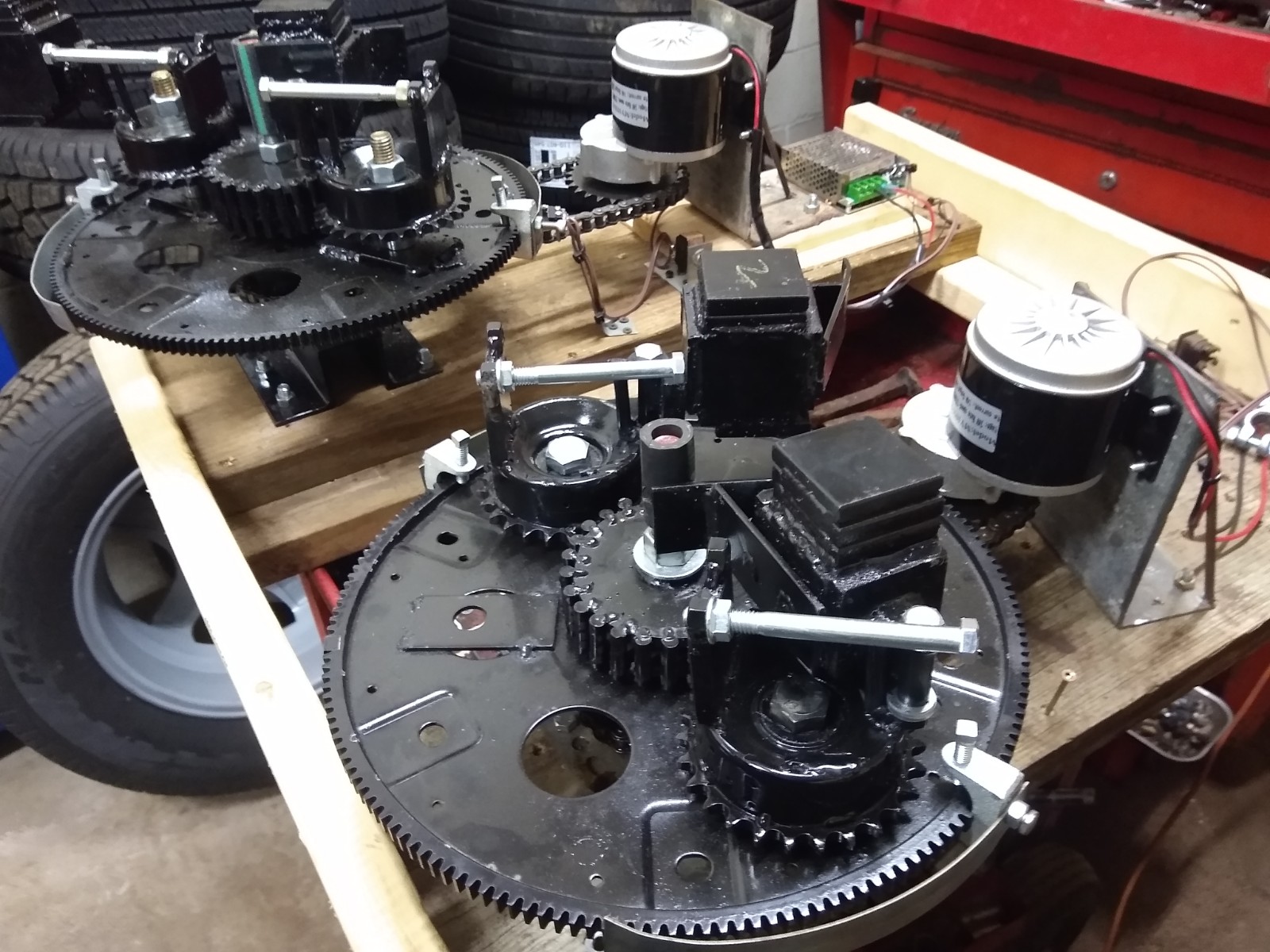
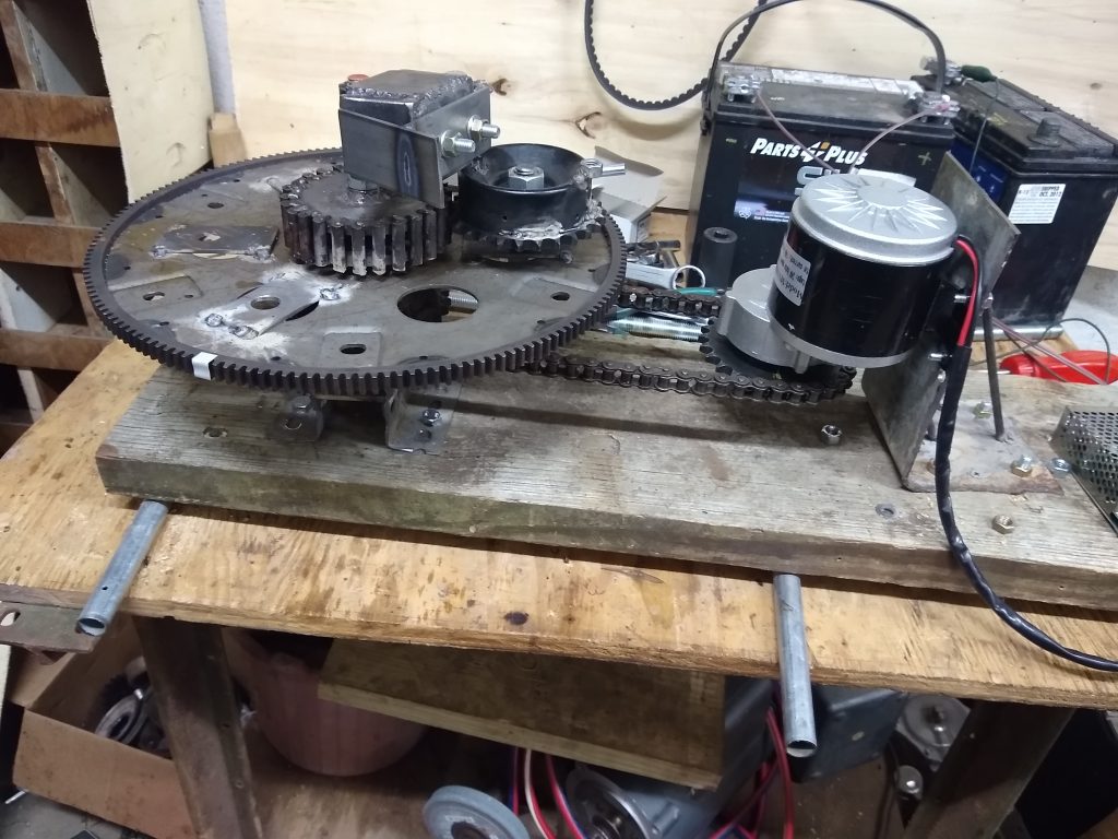
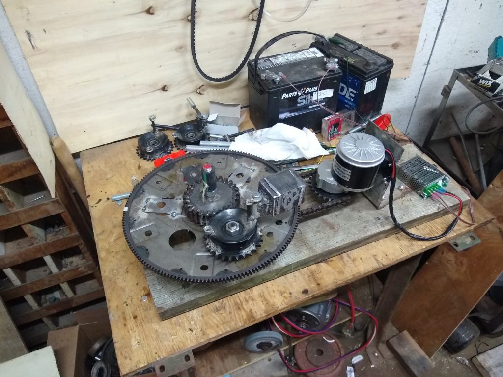
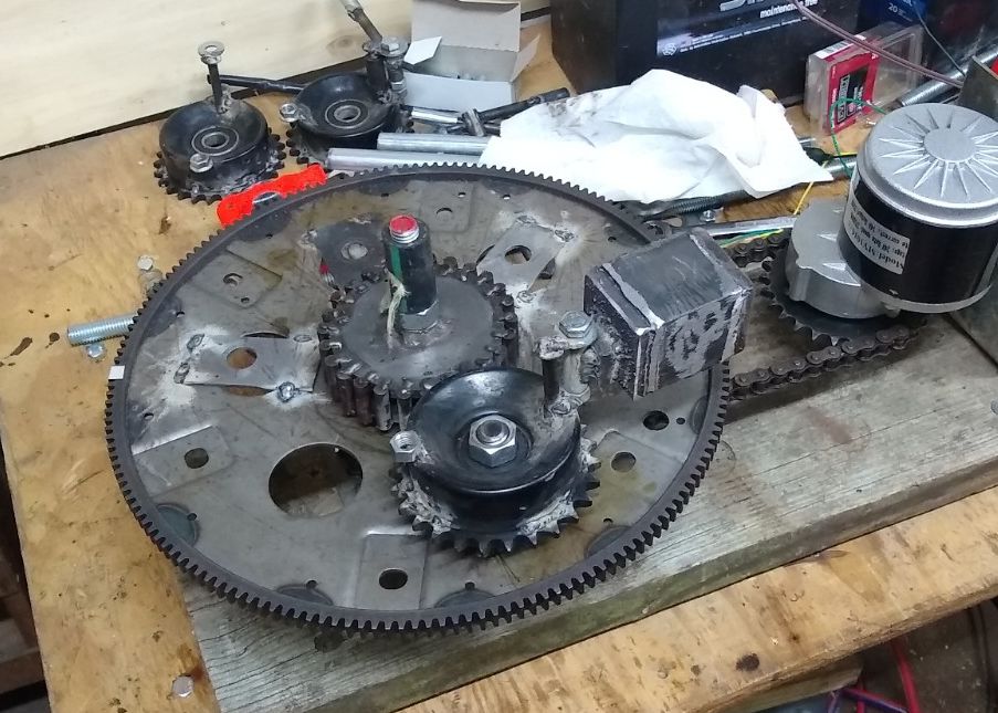
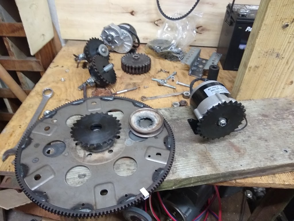
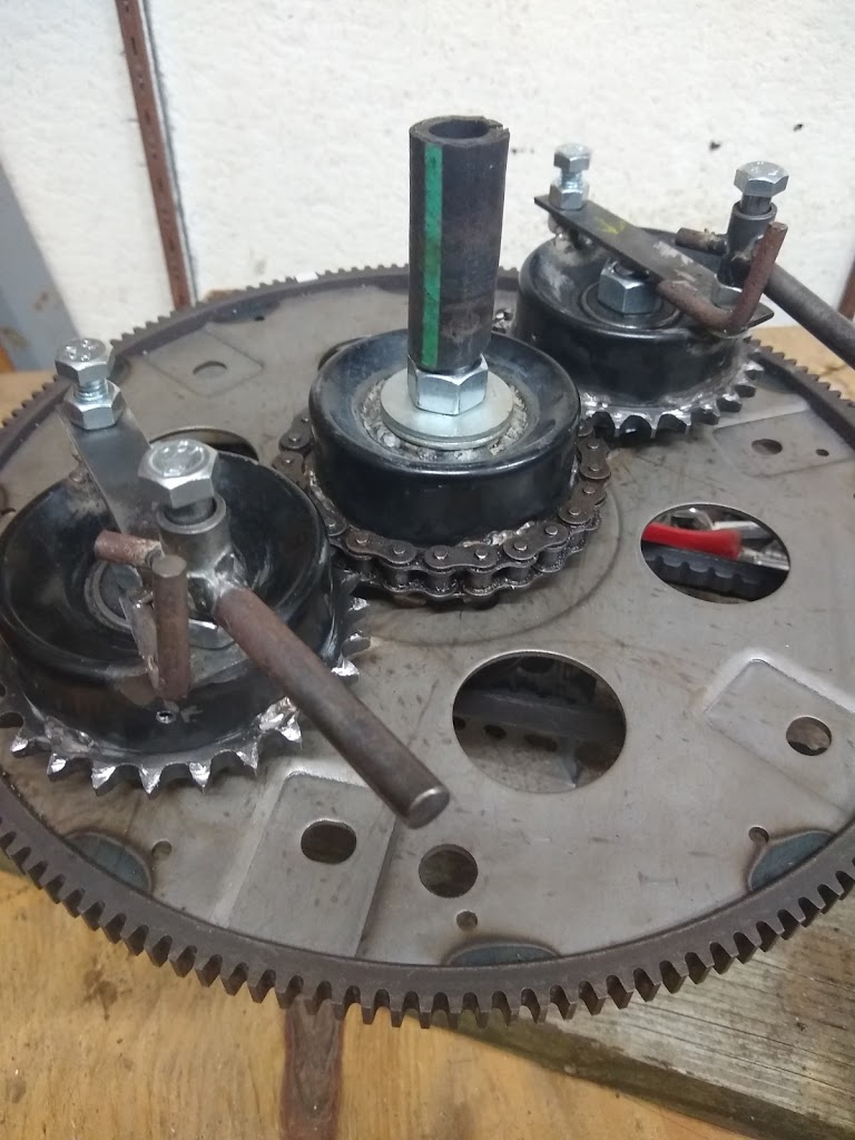
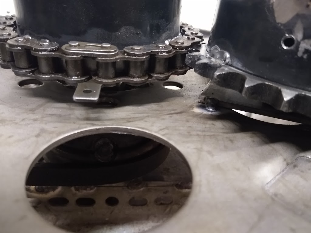
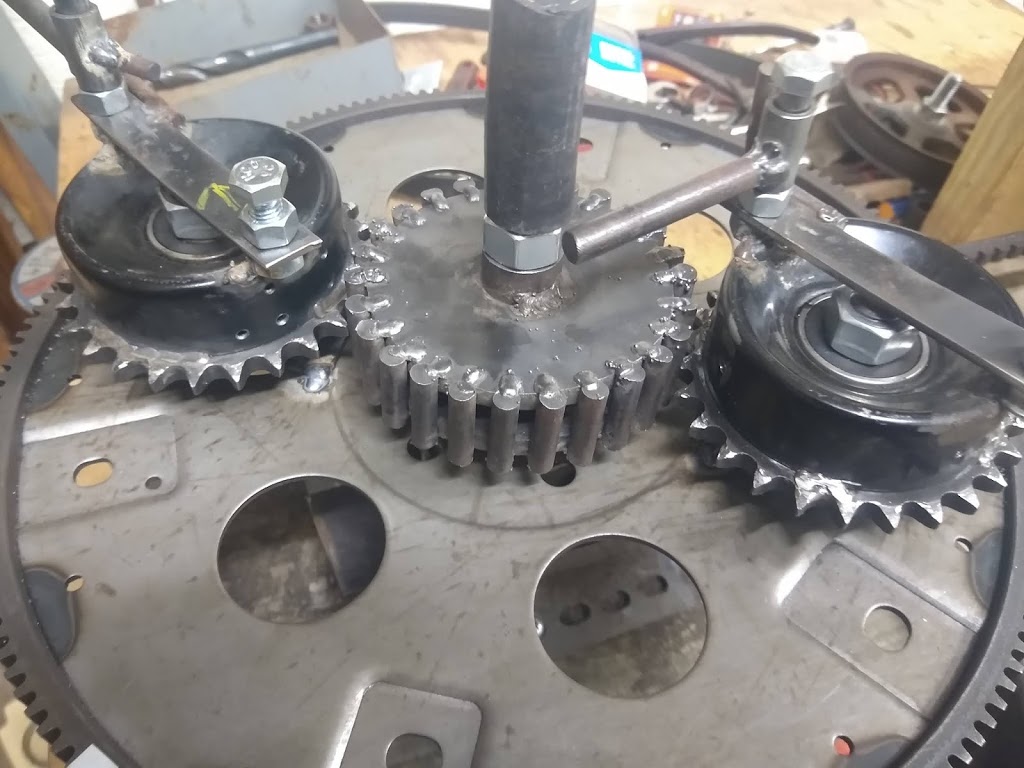
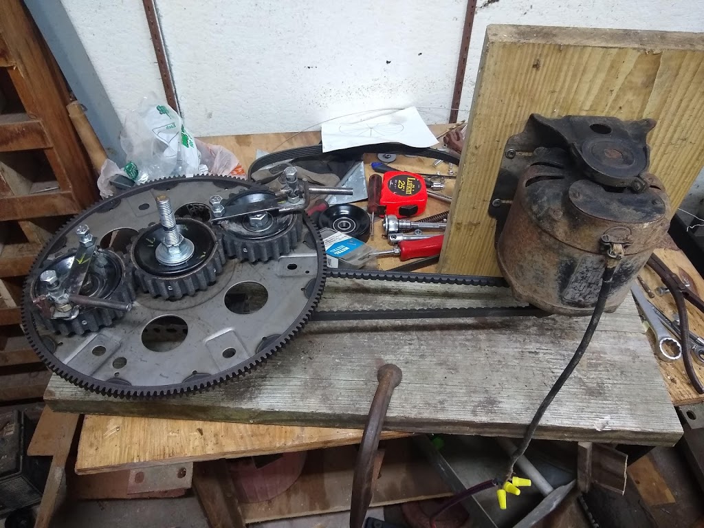
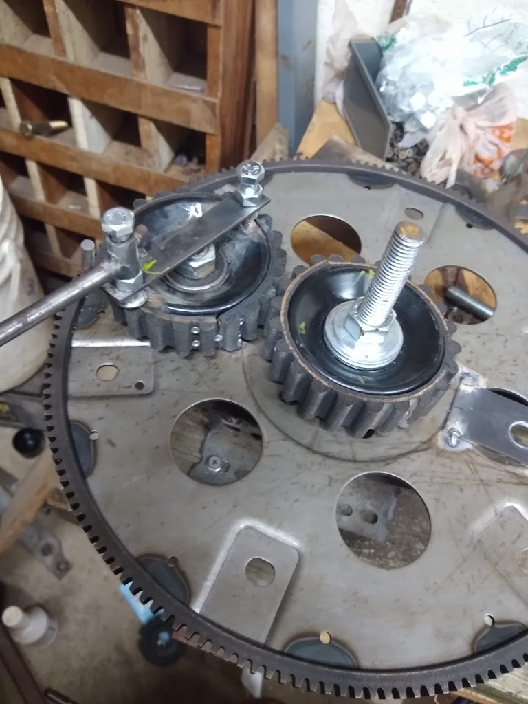
The PIE 6 is really two single-disc PIEs stacked on top of each other in a single framework. The two PIEs are timed 90 degrees apart to smooth the thrust pulses. Previously, this has proven problematic as the pulsing of one disc (or wheel) would detract from the pulse of the other disc when timed this way. The problem seemed to be that the rotational speed of one was directly affecting the rotational speed of the other. Also, the forward pulse of either disc was theorized to be affecting the building of energy in the other disc.
Two different design changes were proposed to test the validity of those 2 theories. The theory concerning rotational speeds seemed more realistic as rotational velocity manipulation is important to the efficacy of the design.
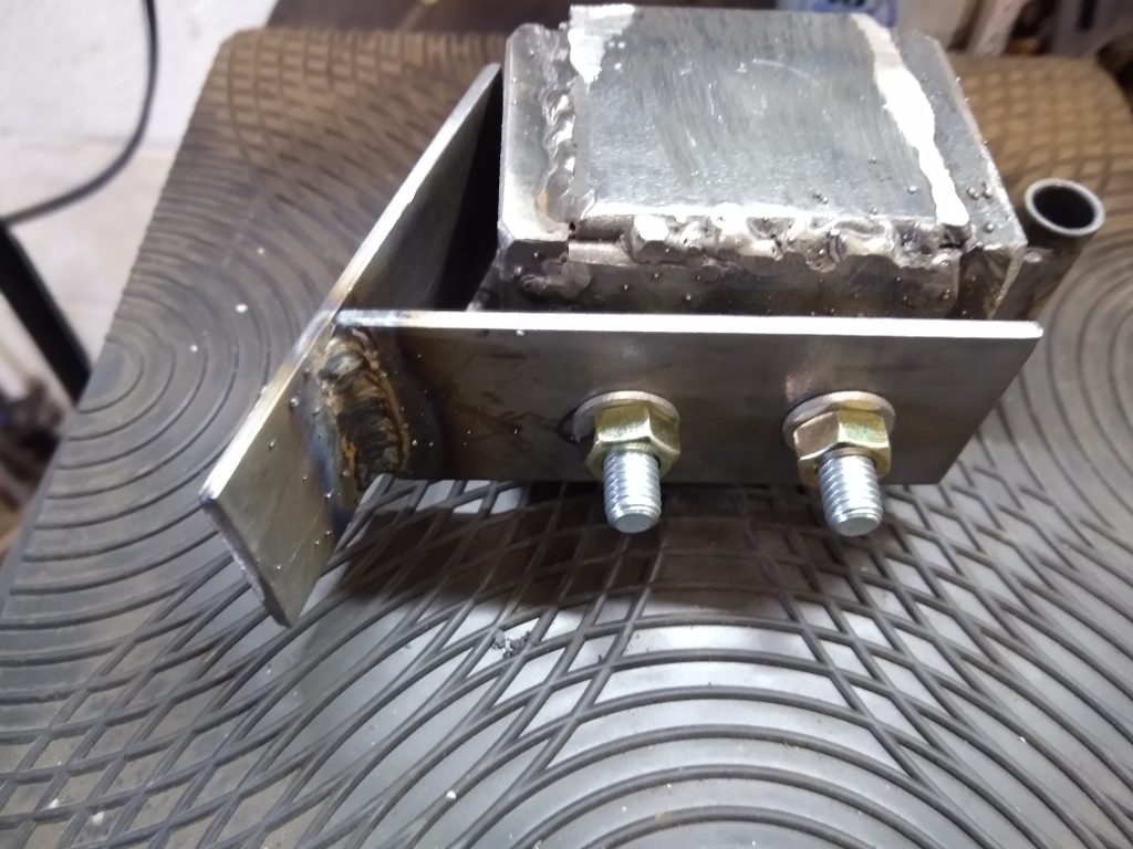
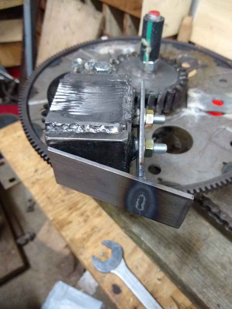
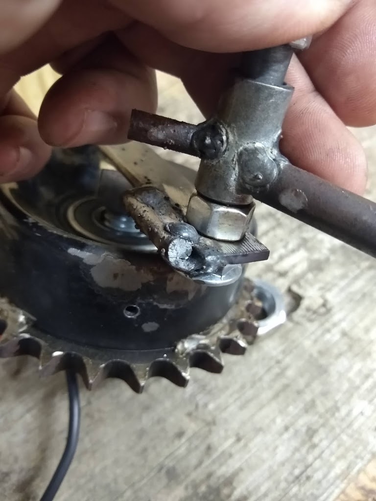
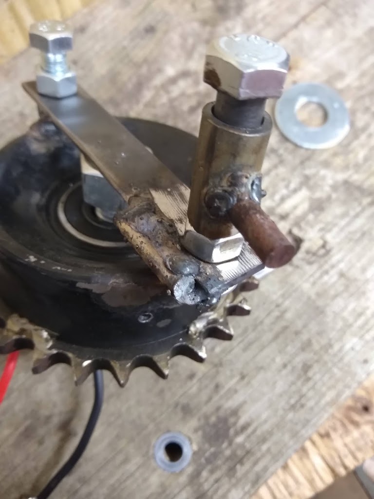
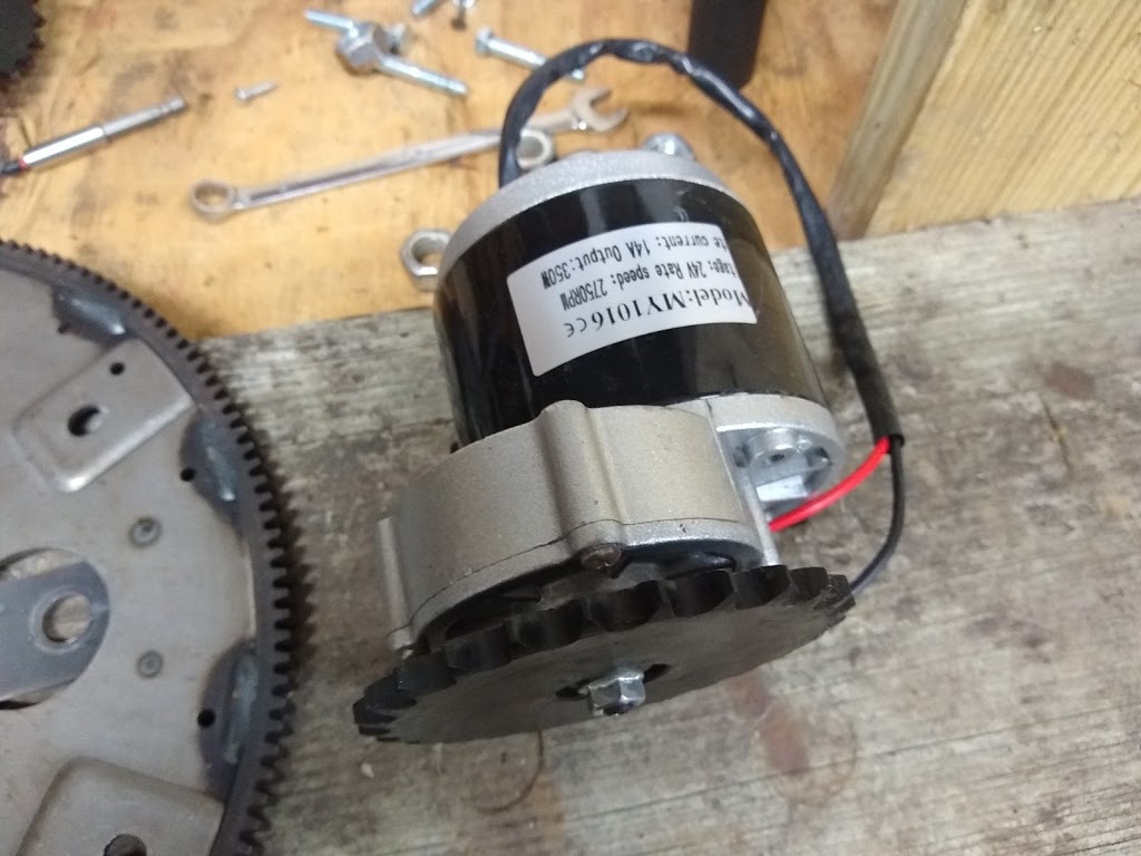
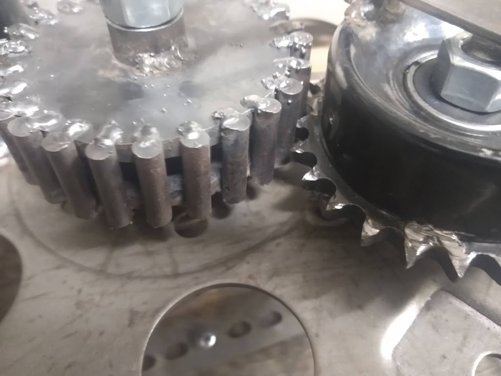
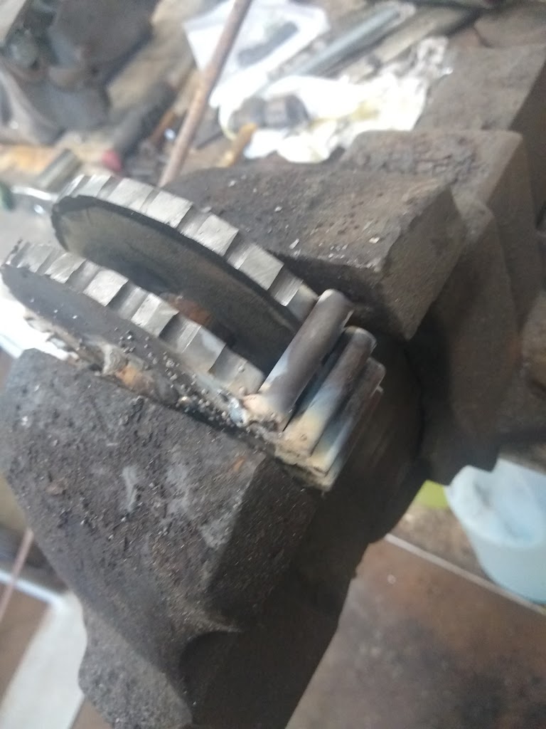
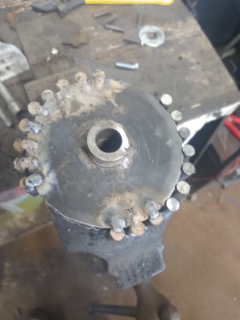
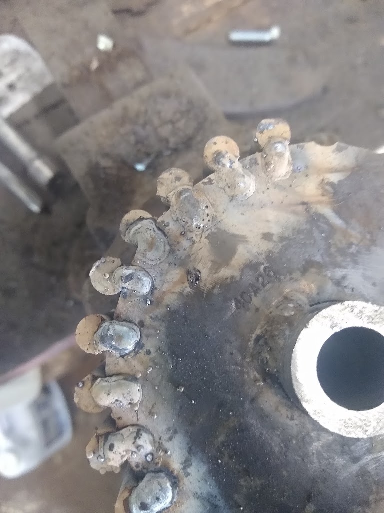
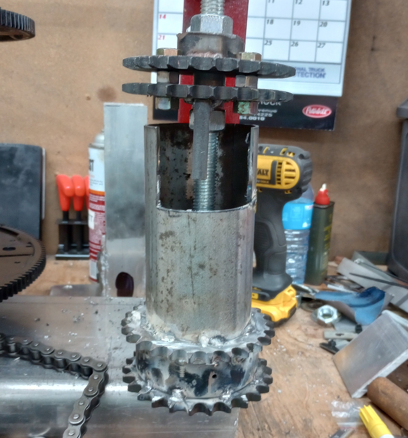
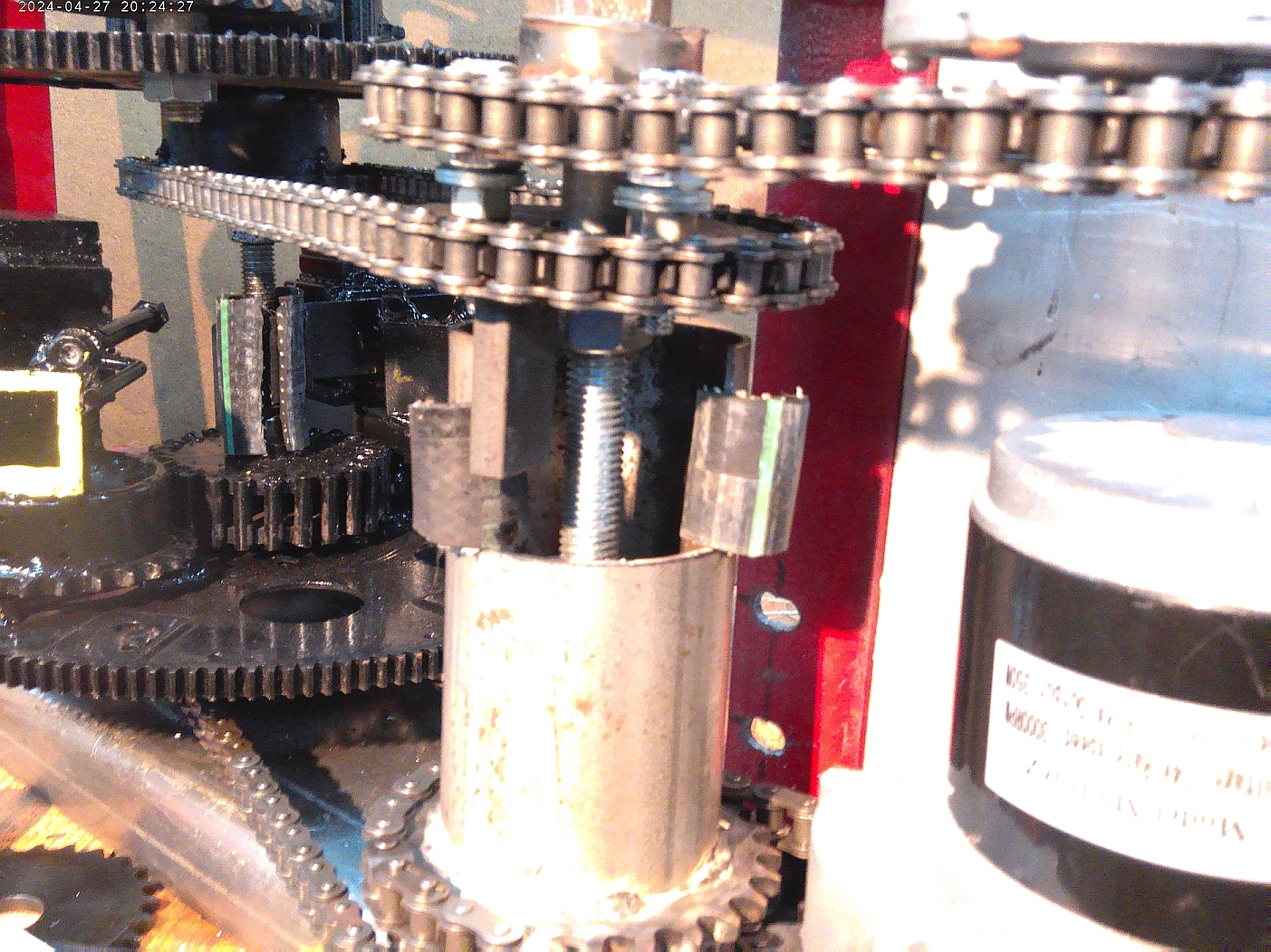
The Quantified Backlash Drive coupler (QBD coupler) allows the 2 PIEs to work somewhat independently, while keeping the initial 90 degree timing within an acceptable tolerance. This whole effort is only to smooth the pulsations of thrust without reducing the thrust of each rotating assembly.
Proper testing of thrust on the test vehicle will now be conducted to satisfy the scientific requirements to validate the design. Even without proper thrust validation the QBD coupler’s success is allowing the PIE design to be enhanced for maximum power. Perhaps a pair of 30 inch rotating assemblies with 15 pound masses! Maybe not exactly, but you get the picture.
This is now making me wonder how many “failed” designs might have been successful if they had used multiple independent rotating assemblies tied together with something similar to the Quantified Backlash Drive… It should be making us all start seriously thinking about it!