As I have been posting here, I have been building the Trammel engine for over 2 years now. I have had some successes, and some failures, and right now I have to admit that I am a little “stuck”. In order to “pull back” a bit and shift focus slightly to a new PIE. The PIE 6.0 is using a lot of knowledge gained from building the Trammel. As before, the PIE 6.0 will be another “open source” project, so, here we go…
March 30, 2024 was the beginning of the PIE 6.0. The 6.0is bringing together multiple working designs of PIE, some of the parts reclaimed from earlier builds, and multiple bits of knowledge gained from the Trammel engine project.
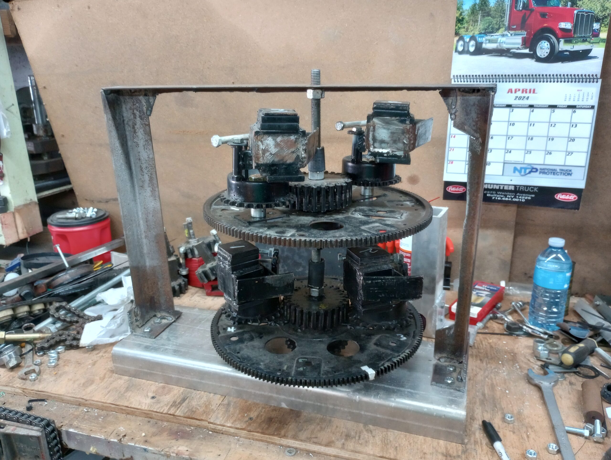
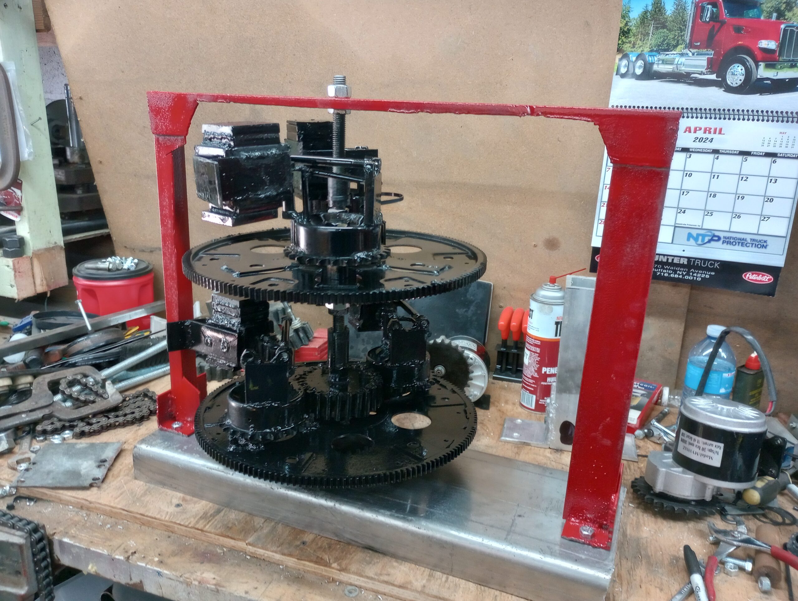
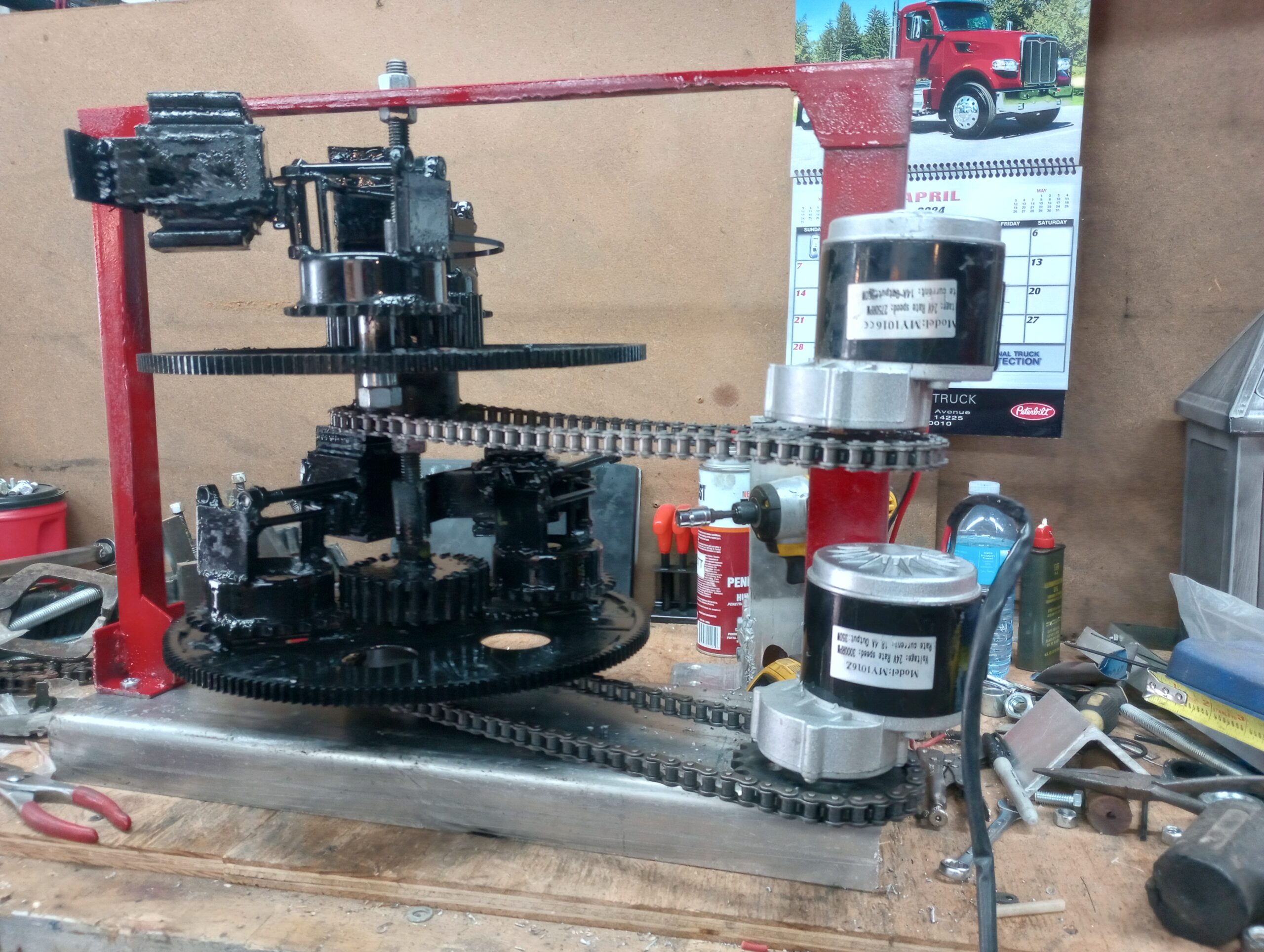
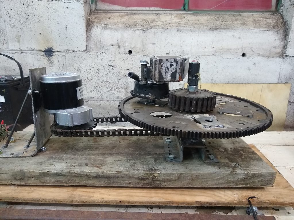
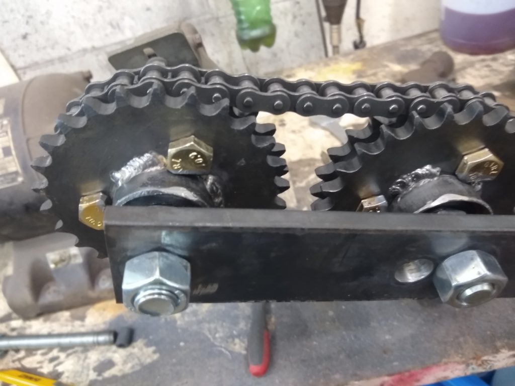
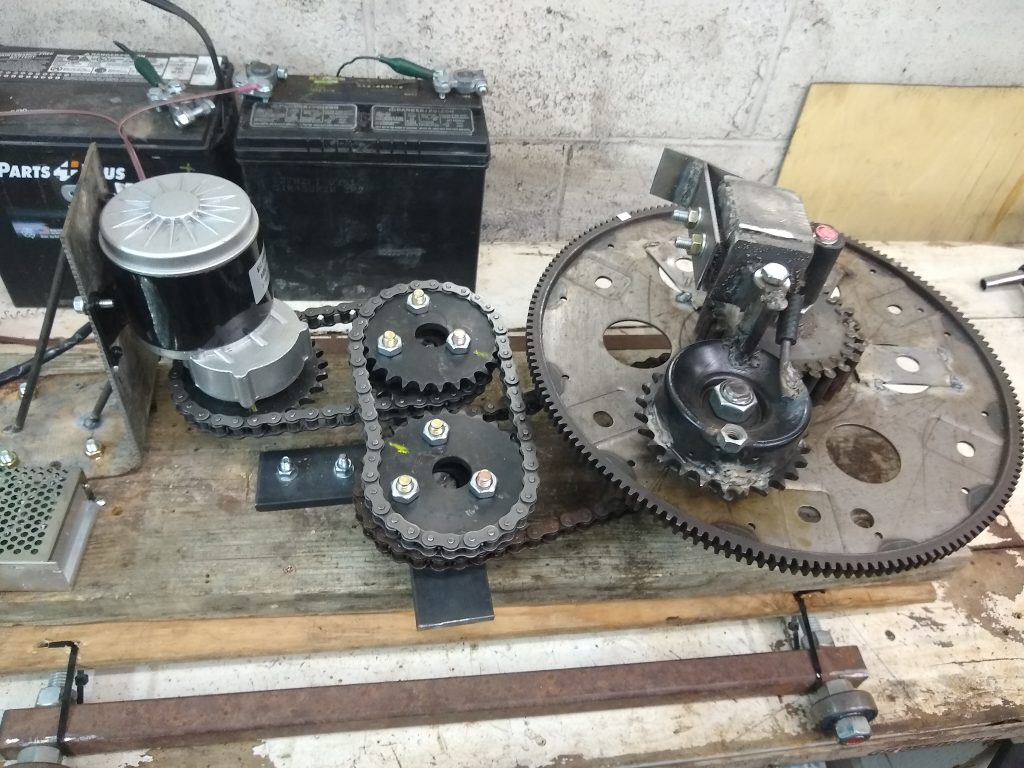
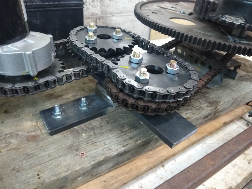
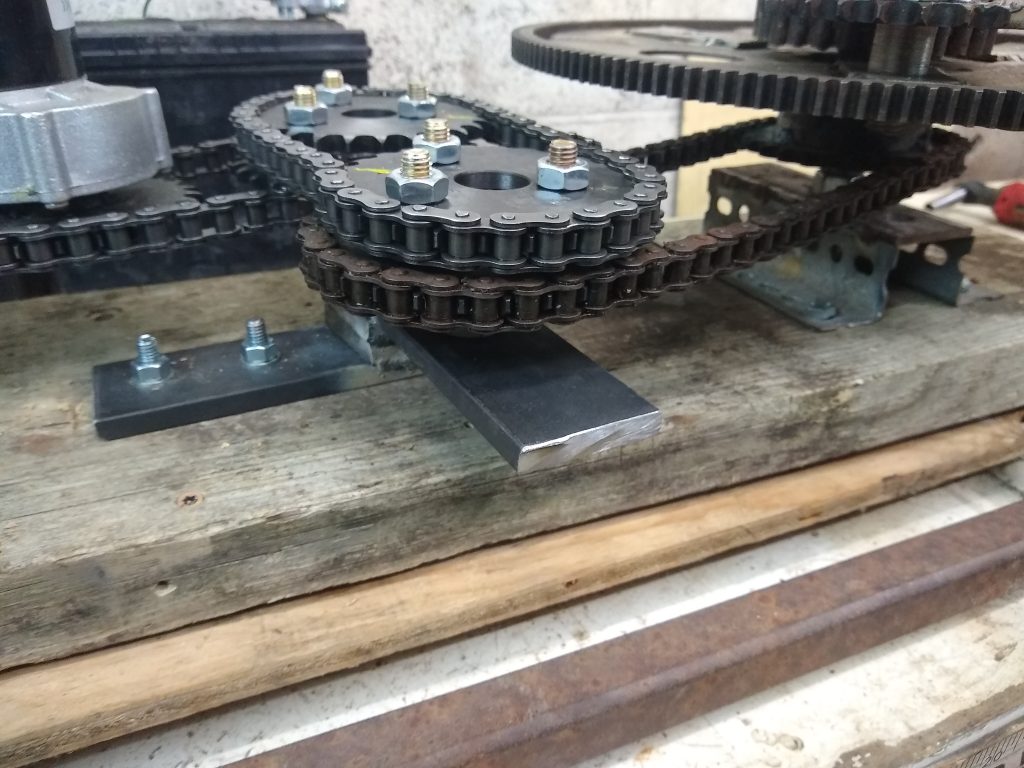
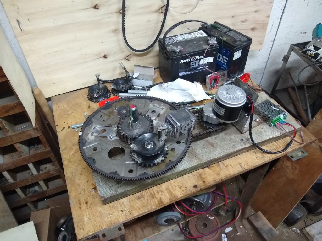
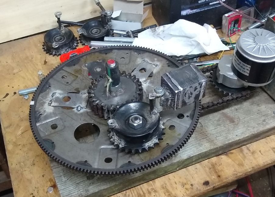
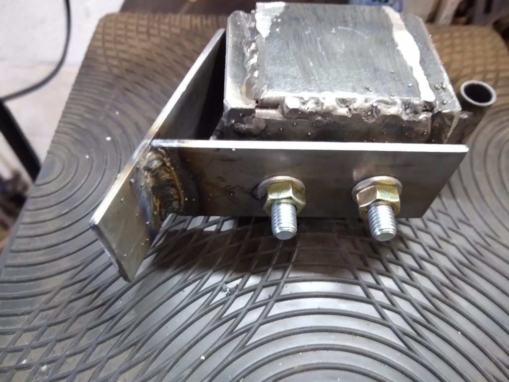
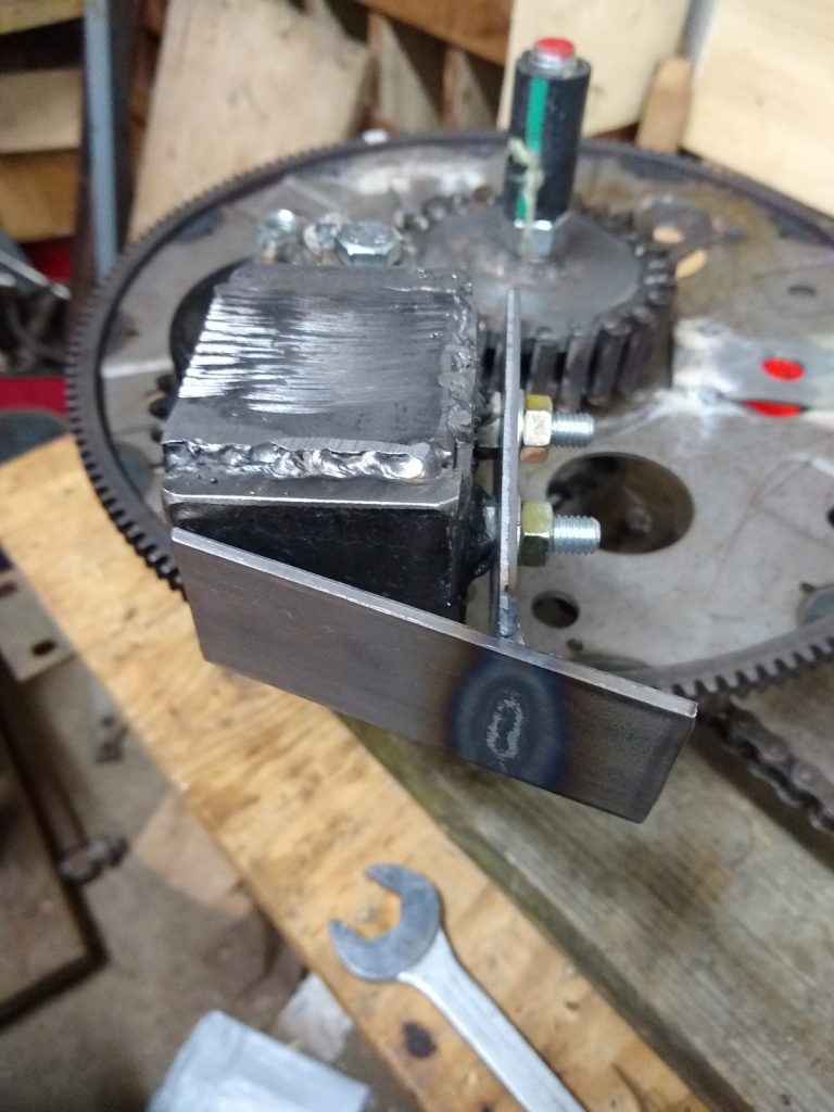
The similarities: The 6.0 is using “dead-blow” weights, we need to refer to as “active masses”, and it is using the stacked “double-decker” design of the PIE 2 series. It will also be using the powerful little brush-type motor(s), speed controller(s), and SDCs (Speed Differential Controls).
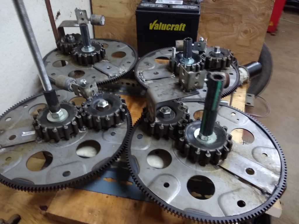
The Differences: The 6.0 is planned to be using 2 motors and drive assemblies, one for each disc (“disc” is a more accurate description than “wheel”). There is a planned timing mechanism that will keep the discs working together while allowing them to also utilize the flexibility of the independent motors and SDCs. There is also a proposed frame pivot assembly, to be explained later.
The Need for Changes: The PIE design is a good example of something that works, but it isn’t readily accepted to be used “as-is” due to the prolific “pulsing” it produces. Previous efforts to improve the “feel” of thrust produced fell short of that goal, so efficiency and “harshness reduction” are the primary goals. There is still going to be noise, I am not focusing on that right now as it is much easier to control with simple modifications to gear designs and sound-deadening covers (hoods).
Stay tuned, we have a lot happening very quickly now, photos below!