Revisiting and Updating the PIE 2.0 into a PIE 2.1, PIETECH P. 14

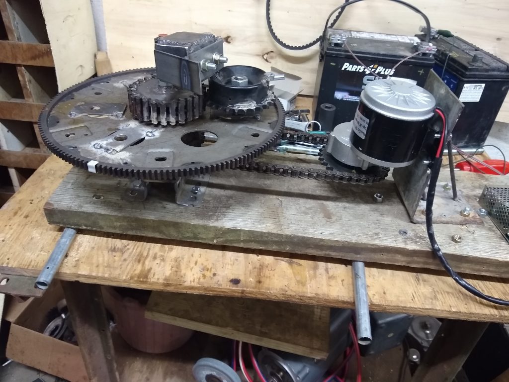
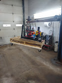
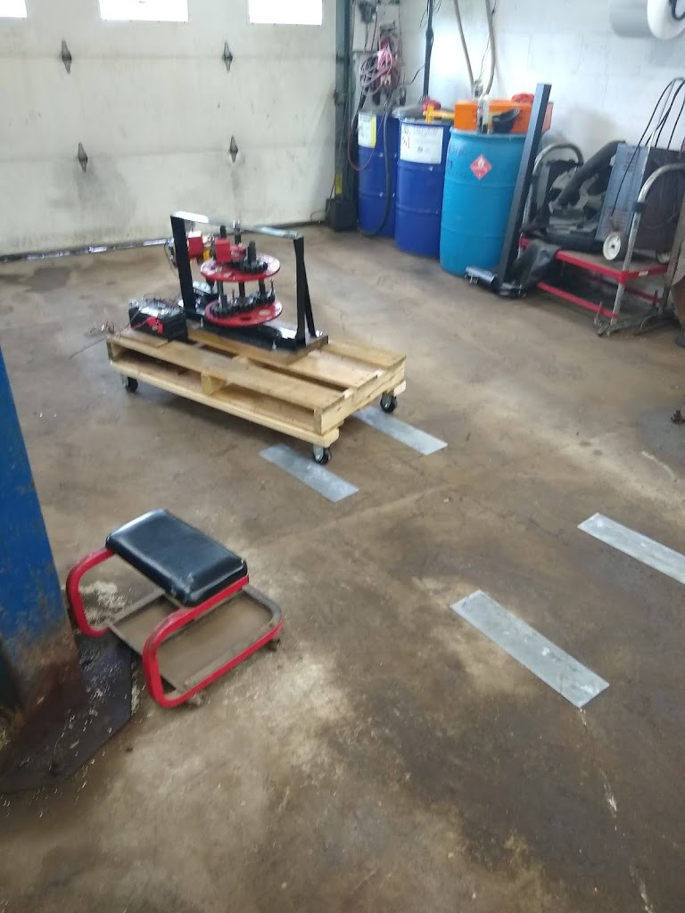
Because the PIE 2.0 was shelved without any disassembly and was kept in-tact from its last tests and demos, I decided it would be interesting to install the 24-volt electric motor and speed controller on it. It was really great to see the PIE 2.0 spring to life with a renewed vigor thanks to the powerful motor. But this was not the reason for upgrading the version number…

Motor Swapped on the PIE 2.0

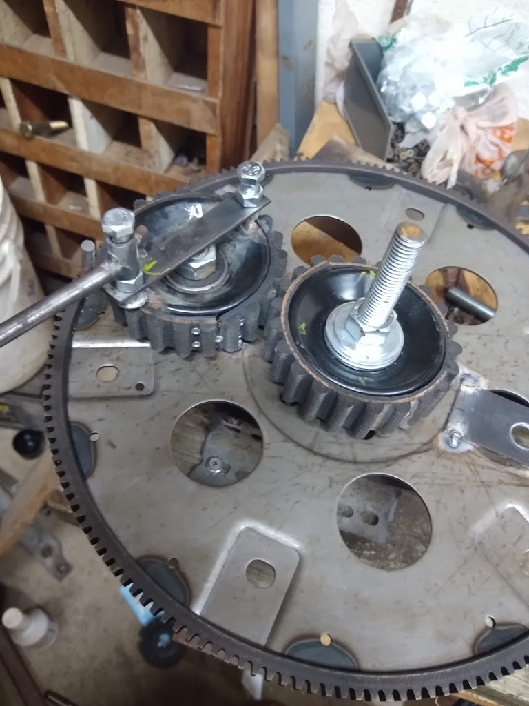
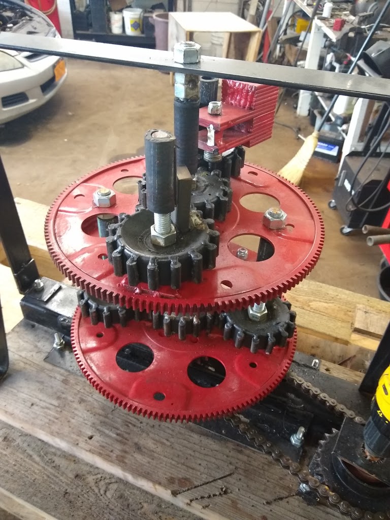
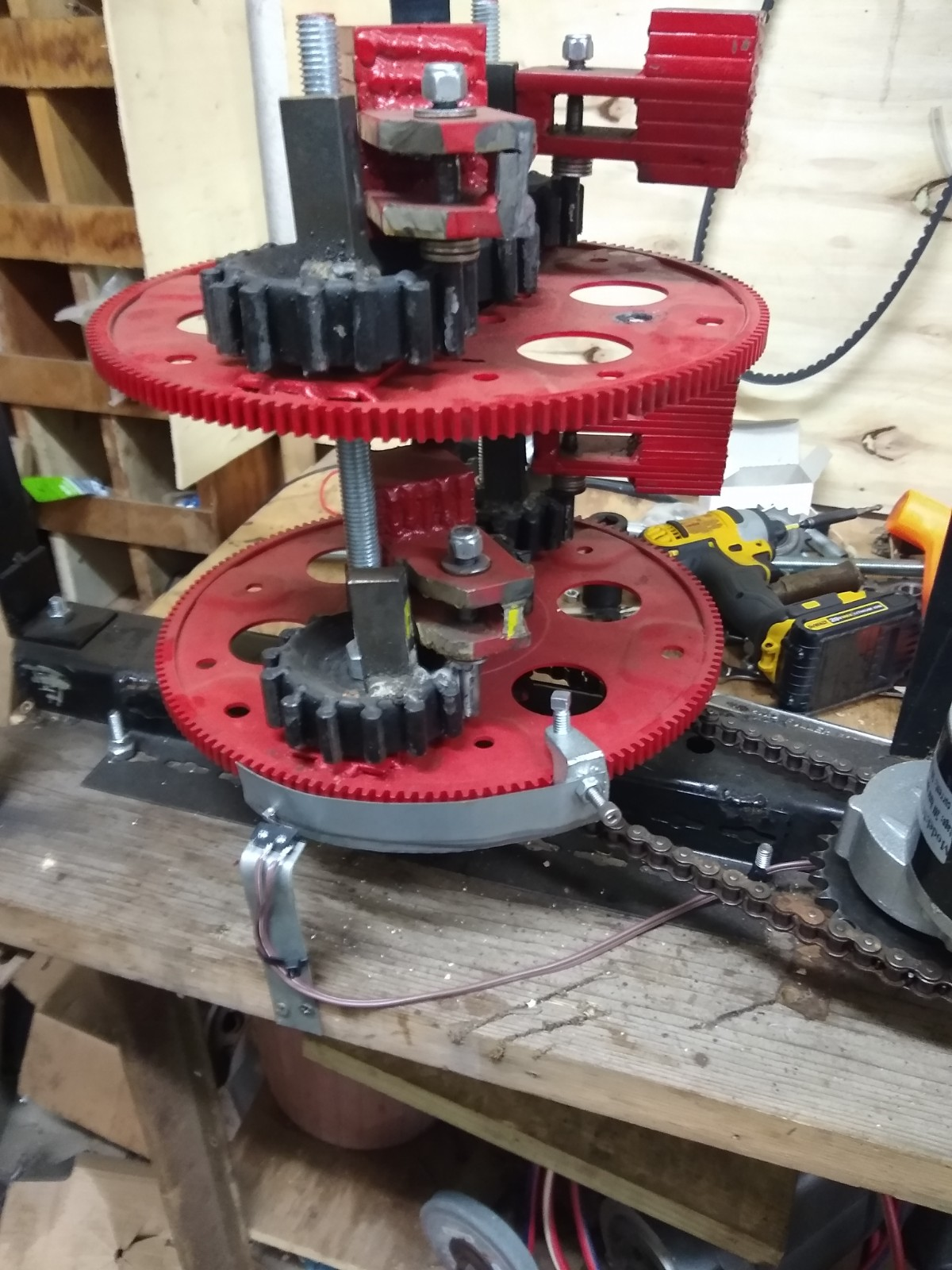
Since the motor and speed controller was working so well (on 12v) it seemed natural to add the speed differential control (SDC) to it as well. I started with one actuator, so the PIE would get a speed boost for one half of the rotation which uses two weight pulses per revolution. This would tell me immediately several things. It would indicate if the SDC would be effective on another PIE (repeatability test) and if it would still work with an opposing weight approaching and entering the “neutral/reset” position.

SDC Installed – The PIE 2.1 is Born

Both results were 100% conclusive that the result was a definite increase in power output!

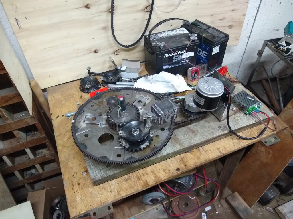
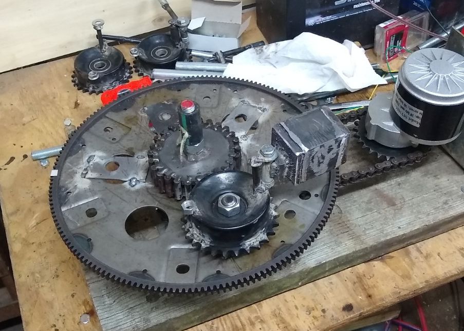
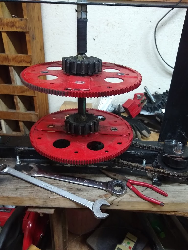
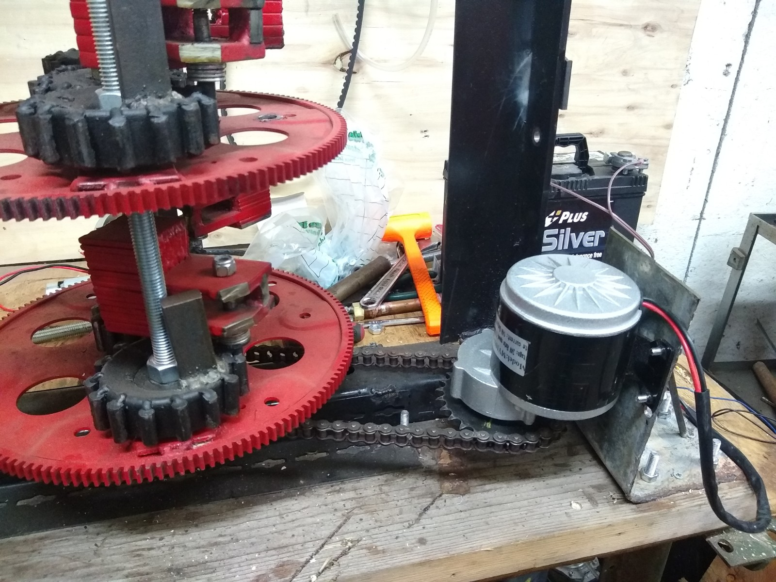
Next was to add a second actuator so the boost would be working with each half of the rotation. A second actuator of identical length (8 inches long) was installed 180 degrees away from the first actuator. Power output seemed very high but because I don’t have a force meter, I simply was not certain. The simple answer was to add a toggle switch in line with the SDC circuit to simply turn the SDC on or off while running the PIE.

PIE 2.1 – With Dual Activators

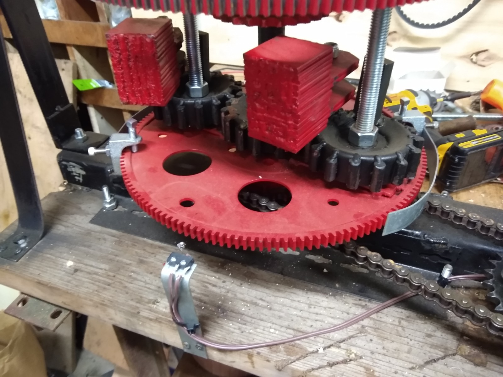
Results of the dual actuator test was amazing! The base speed could be run from 0 to over 100 RPMs, and the action was the same as it was when running on the drill motor. At different speeds ranging from approximately 30 to 100 RPMs, the differential circuit was activated and deactivated at many different base speeds with very powerful results. Judging only by the amount the PIE was moving the bench I would estimate an approximate 50-75% power increase with the SDC active! THIS is the reason I am calling for the version increase from 2.0 to 2.1 on the older PIE.

As a side-note, the PIE 2.1 runs “smoother” with the SDC, and will probably last longer too!

It is now time to “ramp up” the experimental PIE 4.7 with a second weight, and maybe increasing the mass of the weight(s) to around 2kg. In order to do this mass increase, each weight will be using slightly more than 16 linear inches of 3/8”X2” steel along with the BBs, bushing, bolts and weight mounted guide.

New Dead Blow Weight In Process – Empty Cavity To Be Partially Filled With Steel Shot

As the PIE becomes more “refined”, the total monetary cost of each build increases along with the increase in output power, but when overall quality increases the cost will invariably increase as well.

Videos of the PIE 2.0 changing into a version 2.1 are available on my YouTube channel now, and will also be on BitChute very soon.

First Propulsion Bench Test for PIE 4.6

I had intended to wait and do the first true propulsion test on the 4.6 on a proper set of bearings or wheels, but I found myself with a few minutes of free time so I went into my lab area to think about “next moves” & decided that I simply wanted to see it move on its own.

So, it was nothing fancy and the battery was not “riding” along with it. No numerical data was recorded either. I simply placed two short (about 12”) lengths of ½” (12mm) conduit under the PIE 4.6 which would allow it to move freely forward and backward.

PIE 4.6 First Propulsion Test

The RPMs were slowly brought up from zero and as soon as the weight started to swing properly the PIE 4.6 moved forward only, and with a great deal of authority. I was VERY pleased, and I was truly amazed at the lack of backward movement which I am attributing to the dead blow design. I will be posting a video very soon (might be posted by the time this is being read) so please check my YouTube & BitChute channels. https://www.youtube.com/user/stclairtechrd  and https://www.bitchute.com/channel/miGkQfBM24NZ/

I will be making a couple more of these amazing Dead Blow Weights with its attached Guide (DB-G) as soon as possible so that I can see if the 4.6 will still move properly with multiple planet gears using the DB-G. From there, multiple wheels would be on the agenda along with experimentation much like those performed with the 1.0 and 2.0 such as synchronous rotation vs. counter-synchronous rotation etcetera.

It has been mentioned that the slow progress and multiple videos posted with little success tend to be frustrating. This is the methodology employed by the scientific community and by professional Model Makers worldwide.  Even though I know what I want to build, taking these slow and methodical steps allow me to eliminate component designs with inferior performance and focus on those designs with more promise. The more successful designs, to which I am adding the PIE 4.6, are the fruit of this painfully slow methodology. Regardless of anyone else’s personal beliefs (all are welcome to their own beliefs) I also acknowledge a divine inspiration fueling my own personal path of growth in this lifetime.

PIETECH Page 9 – PIE 4.5 With New Dead Blow Type Weight

The latest test of the PIE 4.5 is using a 1 kg dead blow type weight. The weight is a steel box with steel shot (BB’s) inside it. It appears to have a lot of promise, as there is virtually no “bounce” when the weight hits the inner stop, and it seems to be dampened where it would contact the outer stop if it had one (has not been installed).

PIE 4.5 with Dead Blow
Dead Blow Weight Installed On PIE 4.5

There is a video of this first testing on YouTube and BitChute. The problem however remained that the centrifugal force and impact force did not push in the same direction, which was the reason for Thornson’s “Inner Planet Trap” which would hold the weight and release at the correct time.

The answer is to install a “guide” on the end of the weight which would keep the weight near the center axle and correct the problem of thrusting in two different directions. This is proving , so far, to be a much improved design. This can also be seen on YouTube and BitChute.

Guide Fastened to Dead Blow Weight

These improvements are now bringing the PIE version up to “PIE 4.6”.

PIE 4.6 – Dead Blow Weight and Guide

Check out the videos on YouTube and BitChute & thanks for watching!

https://www.youtube.com/user/stclairtechrd

https://www.bitchute.com/channel/miGkQfBM24NZ/

PIE 4.5 and My Original Thornson Drive Replication

Hi everyone and welcome to my blog’s new home. I hope that this venue will be of at least the same quality as before, and I really hope that the text is a bit easier to read!

I posted a video on YouTube & BitChute of the PIE 4.5 with 3 gears, 2 gears and just one planet gear on it. There is a bit of controversy as to which is better and what configuration should be considered for the PIE 4.5 to continue. Watch the video and you can plainly see the lack of propulsion with better balance (3 planet gears), and much better propulsion with a fully unbalanced wheel (1 planet gear). Of course, getting rid of the jerking nature of the drive is a primary goal along with stronger propulsive force.

I have gone back and reviewed my recorded data, and videos, going all the way back to the very first truly functioning drive still being referred to as a Thornson Drive even though the stop modifications were already being changed and modified to the design finally used in the PIE system. The wheels (4 of them) all had a single planet gear, they were all running more or less in-sync, and it just plain worked. I am going to put the 3 videos I have of this original unit together into one video and post in soon.

Keeping this in mind, and knowing that I really can get a MUCH stronger forward pulse without increasing the back pulse, the goal remains to pulse smoothly (an oxymoron). For this plan to work, I need 2 or more complete PIE units that produce fairly equal amounts of force and that can run in-sync (with a calculated offset) without actually being physically mounted to the same frame.

Stay tuned to this blog and my video channels as I think some exciting things should be happening soon!

PIETECH P.4, Coming Soon, a PITECH Builders’ Manual, Also Continuing the PIE 4.3’s Progress


PIETECH Manual: There has been a “Manual” in the works for a while now. It is coming together well and once it is completed it should be a valuable resource for anyone wanting to experiment with Inertial Propulsion without spending untold hours with trial and error testing and expensive components that may not be exactly what is necessary. I have several reasonably complete drafts sent out to other people familiar with this technology for their opinions and criticism. Below is a preview shot of the Cover and the Table of Contents as it is right now.

I am hoping to have this available before the end of the year!

PIETECH Manual Cover

There is also a section within the manual that explains the mechanisms which create the driving force in greater detail than has ever been published, to the best of my knowledge. Color photos and detailed instructions means that little or no math is necessary to follow along, build a working PIE 1.0 or 2.0, and gain a better understanding of the inertial propulsion principals proven to work via the PIE.

  
PIETECH Manual TOC 


Continuing on with the PIE 4.3: Now I am preparing to expand the PIE 4.3 into a 2-wheeled unit running in the 200 to 300 RPM range. Tests have proven the possibility of running RPMs in the 850 to 1000 range, but the components would need a pretty severe redesign in order to sustain those RPMs for more than a minute or two, so I am planning on staying under 500 RPMs for now.

Component Failure: The damage from running at full speed (around 875 RPM) is significant. Both outer stops were broken (twice each), and the sprocket gears used as the planet gears have many bent teeth.

Much of that damage was incurred when the outer stop(s) broke and the weight could jam the assembly. That is also when timing would jump.

“Overspeed” Gear Damage

Possible Gear Changes: Notably the sun gear is completely undamaged! Since there is no damage there and considering the severe pounding the gears in the PIE 2.0 suffered with only minor issues (spot welds breaking), I am reluctant to purchase expensive spur gears which will absolutely have weaker teeth than my homemade ones. Better welding, and perhaps a coating should make perfectly acceptable gears that will stand the abuse of slinging the PIE’s weights.

Sprockets for Now: I will probably continue to use the sprockets as planet gears for now, but if they continue having damage issues they will need improvements to minimize the problem.

The sprockets I am using in the PIE 4.3, they are 40A26 sprockets with a 1” center hole. When I weld in the rods, I could skip every other space and that would make 13 tooth gears that would be much stronger and mesh with better precision than just welding rods to a flat pulley.

Those sprockets are very inexpensive from https://www.surpluscenter.com (around $3 US each at this time) and they are easily welded.

40A26 Hubless Sprocket

Adding to the PIE 4.3: I now know for a fact that the PIE 4.3 produces 20 oz. of thrust at 275 RPMs, and it runs smoothly at that speed. A second wheel is being added, and it will need to be timed to the first wheel, so a chain drive is being planned out for the drive. I would ideally be able to test with both synchronized “sympathetic” spin wheels and also test with synchronized but “opposing” spin wheels and switch directions as easily as rerouting the chain and having a second set of weights. Time will tell how that works out.

Wheel Configuration: It is VERY tempting to stack the wheels up for this higher speed unit, like the PIE 2.0, but I think it should be a side-by-side to make the switching of directions as simple as possible. I suppose the question should be regarding the placement of the second wheel. Beside the 1st one or in front of it? Perhaps that is something else that should be “changeable” for experimentation purposes as well…

MORE TO COME SOON

Volume 2 Page 15, PIE 4.0, The High Speed PIE:

PIE 4.0

The latest incarnation of the PIE is kind of a step back to an earlier design as well as a step forward to push the limits of PIETECH possibilities.


I am using a single wheel (for now) with a much lighter weight, even lighter than the PIE 1.0 design. I am trying out a quiet gear set which uses a 14mm pitch timing belt as the teeth which is fastened to the same size (3.5″) steel pulley as used on the PIE 1.0 & 2.0, and although it is quieter I am not sure if the teeth are robust enough to use as a spur gear.

Initial testing of the PIE 4.0 is very encouraging, although there are some small issues arising from the increased speed which has currently been measured at just over 750 RPMs. The most serious issue has been the used motor I pulled off of the storage shelf. Although the 110 volt motor was marked as “Good” because it runs well without a load, it quickly overheats and shuts down when it is turning the PIE4.0. The other issue is the soft gear design which seems to work well most of the time, but has “slipped” out of time on several test runs. I may revert to the welded steel gears before I am done since I still do not feel that purchasing expensive spur gears in this size range, just to risk having them destroyed if the design fails elsewhere, is an acceptable risk. Eventually I am sure that it will become necessary in order to achieve high speeds for extended periods of time.

The lighter weights (2 oz. including the pivot bushing) are actually performing better than expected as thrust becomes readily apparent in the 100 to 200 RPM range, although a better study of this is required.

The PIE 4.0 has only been bench tested so far, but it easily moves my bench around when it is clamped to the surface of it. Since the PIE 2.0 was just barely able to move the bench, I am encouraged to keep pushing forward with this high speed unit.


Comments about Comments, and Thank You

I have received a number of comments on YouTube, Bit Chute and by other means regarding the inefficiency of this design, and how other designs are soooo much more efficient and can produce these vast amounts of thrust, how this will never work and I am wasting my time chasing this dream.

I have been pointed towards many fine inventor’s works and have had private message conversations with some about some of these.

Here is the deal:

1- I am going to pursue this to some sort of conclusion, it will either be successful or not. 

2- There are those who want this stopped.

3- There are others who think there is a better way but have not built a prototype.

4- There are those who don’t give a crap but like to make fun of other’s efforts.

5- There is always “self doubt” when trudging through the swamp of the unknown.

6- Do not try to force your opinions on me and I will not try to force mine on you.

6- Tell me it can’t be done and watch me go, but do not get in the way.

I was going to post specifics of this here, but I will not. I respect everyone’s opinions even though I may not agree with them.

Please be respectful and comment any ideas you have, they will be respected in like manner.

One last thought today, “Thank You For Your Interest So Far… More To Come Soon!!!”

New Announcements, Global Collaboration, and “PIETECH Electric Propulsion”:


Announcement:

Announcing “PIETECH Electric Propulsion”:

It has been a couple of weeks since my last post, but I do not want anyone to think I am not actively pursuing this quest for universal electric propulsion. The Grassroots Mechanic Movement continues the “Open Source” mission to see this technology advance and freely share information. The Grassroots Mechanic Movement is also in a well controlled growth period which will be branching out creating a somewhat separate entity which will be the “industrial development” branch known as “PIETECH Electric Propulsion” which still needs a logo.

Everything here on The Grassroots Mechanic Movement blog remains free and Open Source always, but PIETECH Electric Propulsion is going to allow the PIE technology to expand into the industrial mainstream as this still-infant technology grows and matures.

Current Work:

Currently I am continuing the R&D work necessary to advance the technology of the PIEs 1 & 2, and I am working towards a higher-speed PIE system that should be capable of continuous run speeds of 800 to 2000 RPMs.

I am also collaborating with other researchers around the world who are working toward a similar goal of cheap, clean, electric propulsion for vehicles of different types. This dynamic research is advancing well and will be announced when those independent researchers choose to allow the release of information (their work, their choice).

I am currently working on an instruction manual for those wanting to build a PIE 1.0 and/or 2.0. This will include specs, dimensions, building techniques, photos, reference materials, and hopefully links to videos. Although this tech is open source, I do believe that there are those who are very serious about building and would benefit from detailed instructions. Any proceeds from manual sales will directly help finance PIETECH research. I am hoping to have this material available by the end of 2020.

Review:

Let’s review where we stand in the “public” development of this technology. I say “public” because it has come to light that these types of tech have been used in satellites since sometime in the early 1960s, but it was just recently declassified… Maybe because of Space-X?

1- We have proven the theories of inertial propulsion are viable, as have others such as Steve Hampton and Mike Gamble neither of whom have I had any contact with at this time.

2- We have also proven the PIE design to be inexpensively reproducible.

3- We have obtained measurable results when used as an electric hybrid power source in a motor vehicle.

4- We have proven that there is no need for a counter-rotating assembly in the low-speed PIE drives.

5- We have proven that rotational speed and timing have a dramatic effect on the amount of thrust (maybe more important than the amount of weight?).

6- We have seen, measured, and proven the effects of both “time” and “timing” within the operation of the PIE. Time somewhat analogous with RPMs and timing is a given physical position within a time frame.

Current Developmental Position:

Now that we have “done it” by proving the concept beyond any doubt. It is time to design a way to put it to use. This means designing a smaller yet more powerful system that delivers clean, stable, and (hopefully) quiet thrust for common use in vehicles.

It has been publicly stated by experts (and I quote one of them) that this type of technology “…will never blast us into space…”, but the same PhD who publicly stated that would not acknowledge the potential usefulness as an electric drive for terrestrial vehicles (wheeled or otherwise). But the advances made in my lab (and others), working on a shoestring budget, and in less than a years’ time, seem to indicate the possible fallacy of that statement.

I BELIEVE that if we work together and collaborate as a community of people, each with his or her own individual skill sets, we can achieve great things!

Some will be mathematicians, while others have great mechanical prowess, and yet others may simply enjoy working on individual components of a larger system. PhD’s and dropouts, mechanics and accountants, pilots and hermits, all working together in harmony toward a greater goal. Impossible? Maybe. Worth trying? Definitely!

When I can foresee components from different systems being used in an assembly together, I feel that I am looking at the future for PIETECH, Dean Drives, Cooke Drives, Gyro Build and others!

Coming Next: The High Speed PIETECH system and Continuing PIE 2.0 Testing…

Volume 2, Page 14, Re-Phasing the PIE 2.0 and Ground-Test #2 – SUCCESS!!!:

Re-phasing for Performance


Since the PIE 2.0 did not perform as well as expected on the “self-propulsion” portion of testing, it was removed from the pallet for rework on the work bench. The phasing of the upper and lower wheels is the primary area to be reworked as the possible answer to its poor performance.

The PIE 2.0 was not built for easy phase adjustments, so the rework included the removal of all planet gears and axles. The rework is a re-phase of the wheels from a 90-degree offset to a 0-degree offset.

It would be much better to change the phase offset in smaller increments (say 10, 20 or even 40) but since this is the way already built into the design, this is how it is being done.

Fast Forward a Couple of Days Later and “Ground Test #2”…

That has done it! The re-phasing has made significant improvements in the quest for “self-propulsion”! It will now work its way across the garage floor under its own power with nothing driving the wheels!

The upper planet gears and the lower ones now share the same axles, and the wheeled trolley has been made robust with a tubular steel frame and metal bearings as wheels.


I am posting 4 self-propulsion videos to YouTube and BitChute to get maximum viewer coverage and get the information out to everyone.

Regarding subject of re-phasing:

There is a chain sprocket on both wheels and that could be used to drive each wheel independently. A drive chain to each wheel, and the chain can be switched tooth by tooth or the drive sprocket(s) can be made adjustable. A split jackshaft with an adjustment mechanism could be utilized to perform phase adjustments “on the fly” without shutting the PIE down.

More to come soon…

Vol 2, Page 13, Ground Testing


Post vehicle, wheeled, ground-testing.

After a short pause caused by things in life that have required my undivided attention, I’m back & ready to get busy.

 So, the on-road testing would be considered a success, and the “hybrid-assist” effect is undeniable. The “failures” encountered within that round of testing were due to the prototype building methods and materials. It is hard to justify the cost in time and materials for a more durable build when it is being taken apart and changed multiple times.

Total cost of materials for a single planet gear, without the weight, is around $8 US. The cost of a machined, straight toothed, drilled hole center, spur gear of the same size is around $200 to $300 US. In that light, the component failures are an acceptable offset to the cost differential. Now we move forward with further testing of the PIE 2.0 while still getting ready to build a next version.

 **********************************************************************************

One thing I have purposely not mentioned are the efforts being put forth by other people around the world to either replicate a PIE 1.0 or 2.0, or to incorporate their own designs into a build of their own. Because of those awesome individuals helping to further this research (thank you again for the help) my next version may be a 4.0 or higher.

 **********************************************************************************

Now I will cover the post-road-testing phase of PIE 2.0 testing. 

Nothing was changed with the setup in any way between removing it from the truck and installing a set of hardware store straight caster wheels on it. The wheels were attached to 2 pieces of lumber (2X4s) and the lumber was attached to the bottom of the pallet with wood screws. Testing was done on a level concrete garage floor surface, and pieces of sheet steel were laid down under the wheels to allow them to roll as easily as possible.


Results were not as good as I had anticipated. Forward thrust was definitely present. When it was running, I could easily push it forward with one finger, but it would not move forward on its own.

 This distressed me greatly, since there is an undeniable and measurable thrust present when used for “Hybrid-Propulsion”. I have pondered this in great detail, and I have several thoughts as to the reason.


1. The wheels roll too hard, and they are also flexing. This combination makes pulsed propulsion nearly impossible.

2. The drill motor is dying. It has worn to the point of reduced torque which means that there is an unwanted & uncontrolled speed variation. Every inertial propulsion design I have ever experimented with has been rendered inoperable at some point in testing because of this phenomenon.

3. Comparing the PIE 1.0 & 2.0 I believe there may be the same issue spoken about with other builder/experimenters regarding timing changes needed to allow a “hybrid-assist” device to be fully “self-propelled”. Since both PIEs work as a hybrid-assist, but the PIE 1.0 also demonstrates self-propulsion I believe this is a solid theory.


In order to prove this theory of the two different “modes” to myself, I started removing weights one at a time from the PIE 2.0 and observed the operational differences. There were some interesting things to be observed, and a lot of very loud noises being made. When I got down to one weight it began to self-propel. It does try to propel itself with 2 weights set 90 degrees from each other, but there is no denying the self-propulsion with only one weight.  I truly believe that this may be, in part, the answer.


My next moves are as follows:

1. Re-phase the upper & lower wheels to bring the weights into sync between the top & bottom.

2. Replace the ailing power source to stabilize the RPMs (as these devices get more powerful a flywheel may become necessary to stabilize it).

3. Get a better set of wheels before the next test!


I will post the results as I go along.