PIE X Being Built Now

I am still around! I am still building! I am not going anywhere!

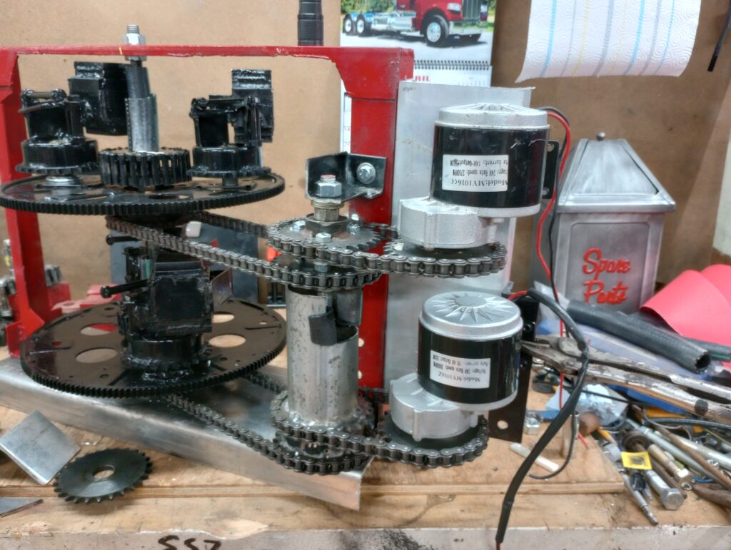
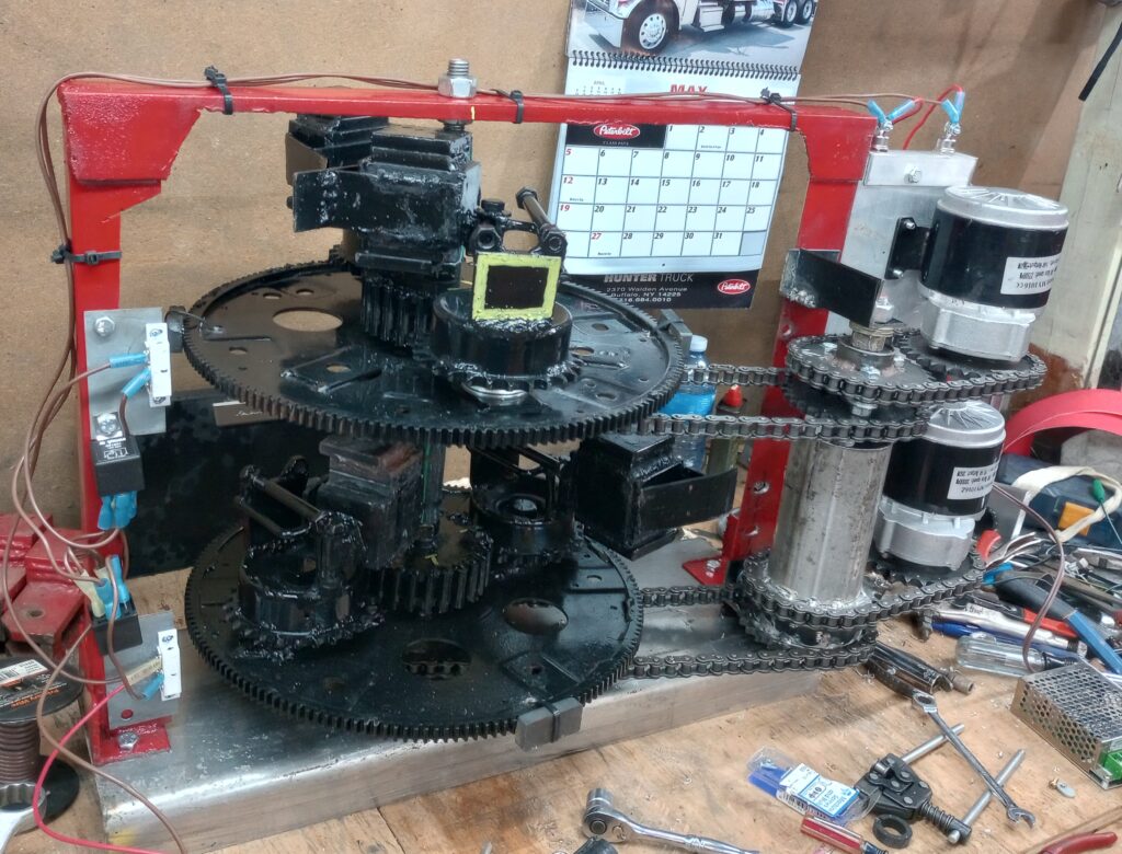
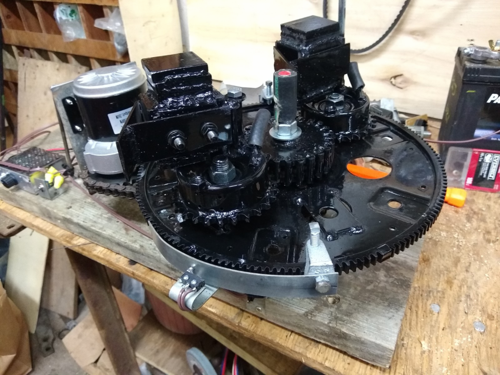
It has been quite a while since my last posting and my last video. I have been hard at work on the PIE X design. I am still not at liberty to detail its design except to say it is based on a series of rotating discs which use specialized components under tension and using a “Mass Displacement” system should create efficient linear thrust. It is still being called a PIE because it does have a pulsed propulsion component, but these pulses “should” happen 4 times per revolution and run at 1000 RPMs or more so the pulsing should be MUCH smoother than that of the previous PIEs.

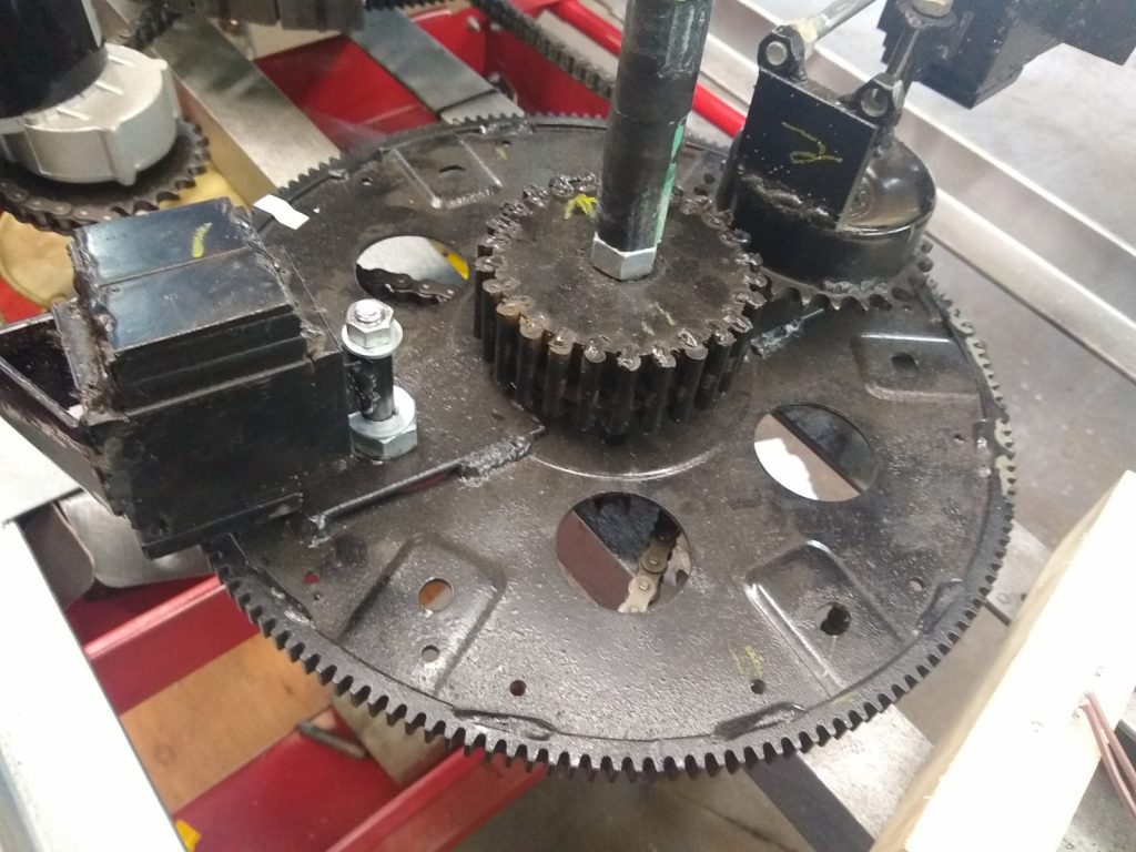
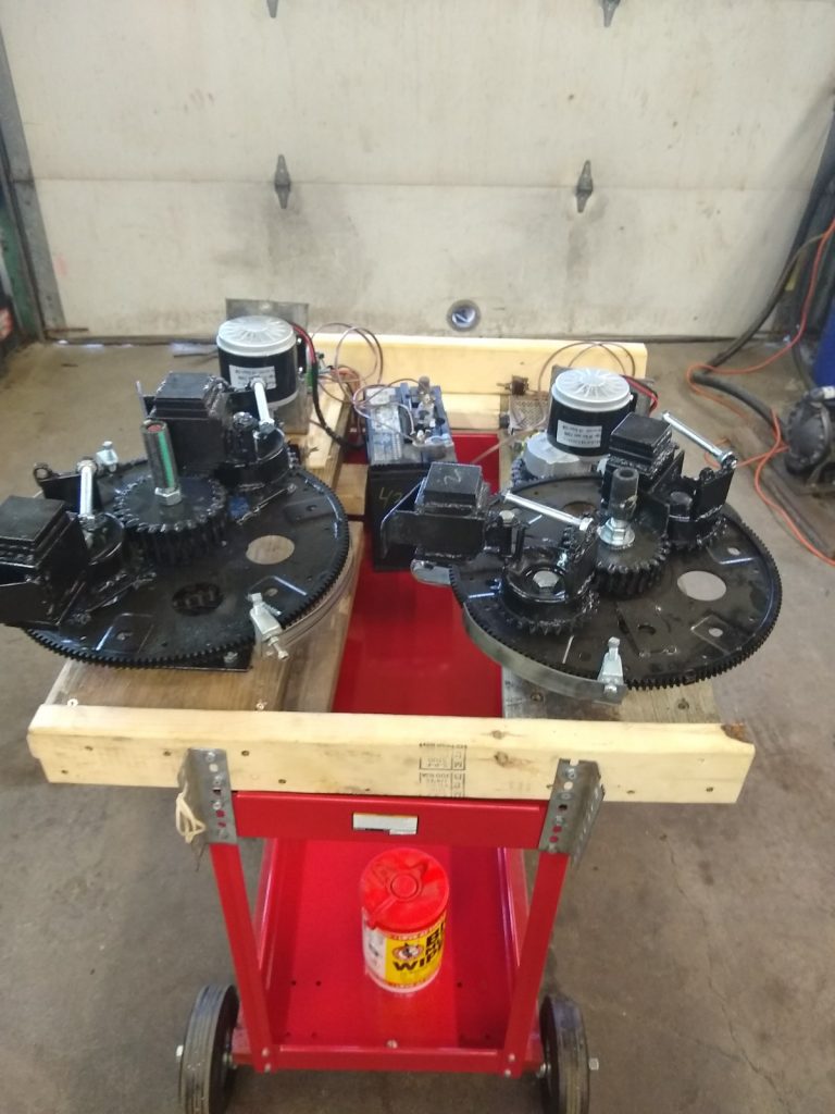
Although this is not my original design, and it has been done before, there are no working devices known to exist and its duplication attempts have all been in vain… Until now. Well, soon anyway! The main unit is framed up and the rotating discs do rotate very well. The specialized internals are partially complete, and testing has had some very positive results thus far!

Without giving details regarding the origin of this base design, the person who originated it stated that they ‘…will not give away all my secrets…” and emphatically stated that others will have to “…figure it out for themselves…” and so we are figuring it out now.

It is unfortunate that the original designer was (and still is) compelled to distance themselves from this technology!

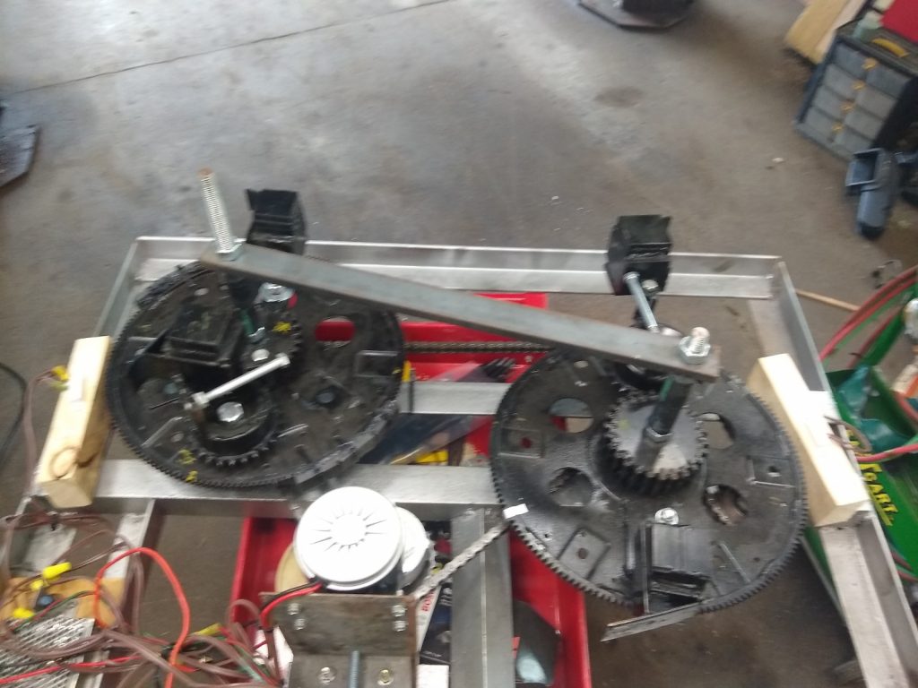
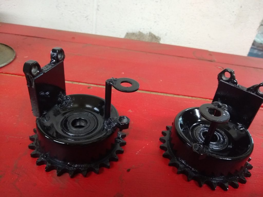
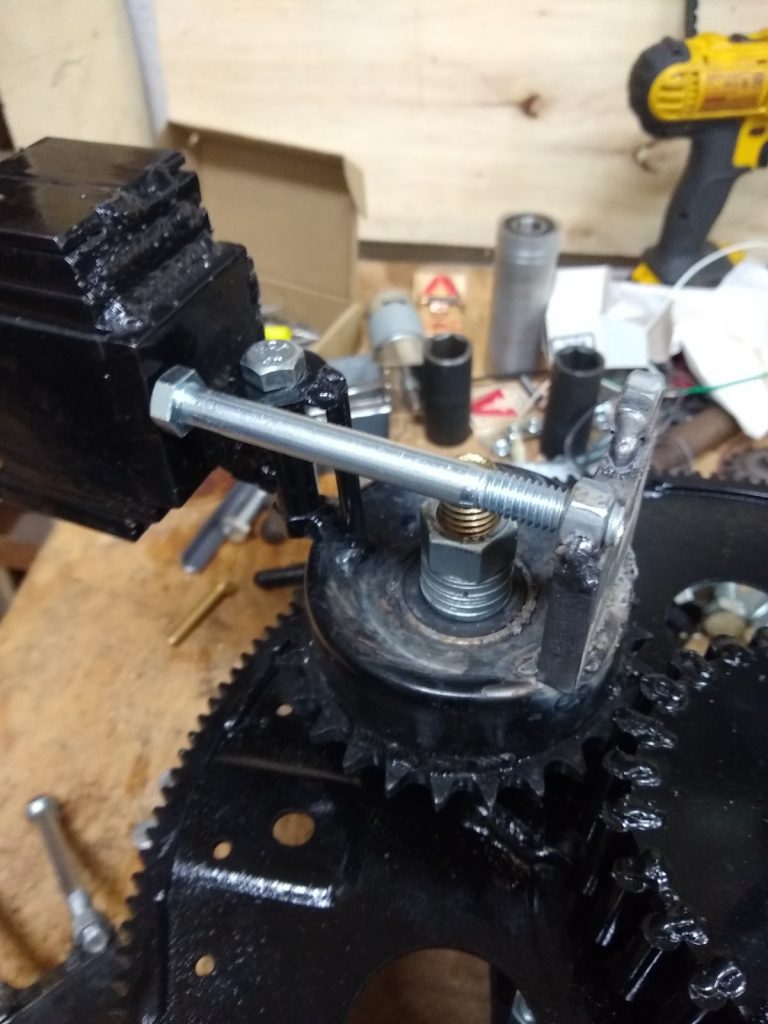
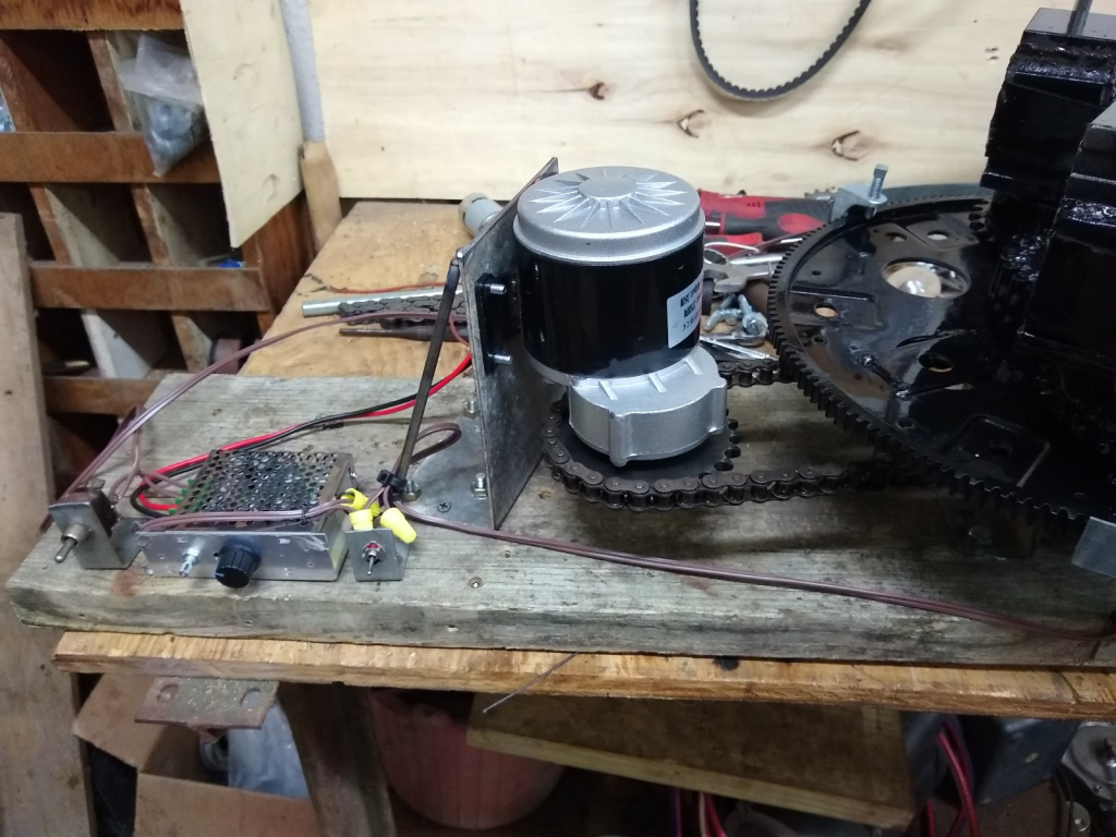
What I can say about the PIE X is that it is using 3 rotating “wheels” which are referred to as “discs” or “plates” and has at least 10 times more parts as the PIE 4.x series has in it, not including nuts and bolts holding the framework together. I can also say that I have built it with absolutely no regard for overall weight. Most of the unit is built with heavy steel components rather than lighter weight aluminum and/or hollow parts. Overall weight has become too much to easily move around as it is well over 130 lbs. and still does not have an electric motor installed. I am hoping that with all the excess mass it has enough thrust to easily demonstrate linear thrust.

Right now I am turning it with a hand crank, and because of a problem with what I refer to as a “backfire” I will not be installing a motor until later. The backfire is 100% mechanical (no actual fire) and refers to a point internally where stresses are suddenly released in the wrong direction and a backward movement happens (inside). This could have catastrophic effects, so the issue needs resolution before a motor can be used!

I did post a rather ambiguous video online with the internal pieces covered (for now)…

First Public Look at the PIE X

PIE 4.8 Changes to SDC and Issues on Latest Test Drive

New SDC Switch

It has been a very busy several weeks since I have had opportunity to update this blog. Work and life have been very busy and work on the PIE has been slow.

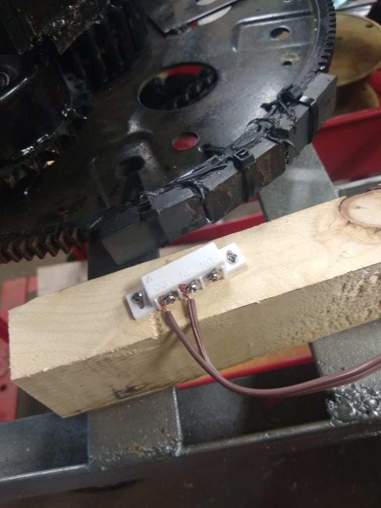
The re-phased PIE 4.8 has had the first road test completed with no SDC as the SDC micro switch is a continuous source of problems. The lever on the switch tends to break or get bent very easily and the roller wheel also tends to fall off frequently, so it was decided to use a “proximity switch” as a non-contact alternative. The switch chosen is a magnetic switch used for building security systems as a door/window open/close sensor. This is easily activated by mounting magnets instead of mechanical actuators and this works very well.

The PIE 4.8 second test drive was, however, less than outstanding. The re-phased PIE wheels and SDC “should” have yielded much better results than the previously phased tests when it was set up for “self-propulsion”, but the results were very disappointing as the engine load reduction was only in the 4% to 6% range.

I believe it has to do with the counter rotation of the wheels. The “zone of thrust” or “thrust zone” on a single wheel is rather wide as it pulls forward through a good 45 degrees of the rotation, by having the counter rotating wheel, the “thrust zone” is effectively narrowed but instead of “focusing” thrust, it only eliminates part of it.

The next steps to calculate the reason for such failure will be to adjust phasing back to synchronous and increase pulse torque by removing one weight from each wheel. The thrust will alternate between the CW and the CCW wheel, this should demonstrate the theory of the wide thrust angle vs. narrowing the zone.

Phased Back and Switched Down to Two Planet Gears

The non-functioning weight is being used as a balance weight. The planet gear that is not being used is removed and the weight is bolted to the wheel in its place which balances the wheels enough to keep it from tearing itself apart.

One Planet Gear Removed and the Weight Used for Balancing Wheel

If this works out, the plan is to reverse the rotation of one of the wheels and repeating tests with co-rotating wheels to increase thrust without narrowing the “thrust zone”.

Ready For Road Test Set #4

On a side note, I believe the thrust zone will automatically be much more condensed (thus stronger) with a different design. Perhaps the PIE X will accomplish this.

PIE 4.8 Testing- and -Doubters, Debunkers, and Haters:

Well now, it seems that with the openness of the experimentation, building, fabricating, and functional videos that the “it doesn’t work” folks have become “it only works because of” folks.

The better we get this working, and the more verified data there is, the more people keep coming up with reasons they think we get propulsion. Primarily this presumptive opinion input has revolved around friction. The common theory is that “contact” with virtually anything is the friction causing propulsion. I cannot say that anything is impossible, but short of tossing this thing out into space it will be nearly impossible to “disprove” that theory! Here is my position on this… “Who freaking cares?!?!?!” It just works, so let us expand on this and put it to use for the betterment of EVERYONE!

I get it that the super smart technical theorists believe that anything that isn’t incredibly complex simply cannot work. Sorry people, but that is just another false theory which has been mistaken as fact.

Mine is NOT the only system that works, mine is not the only tech that needs to be openly replicated. If the replications are done with an expectation of failure, it will most likely fail. If they are done with an open & optimistic attitude with an expectation of recording valuable data, extraordinary things are possible!

PIE 4.8 First Test Setup

I have recently published the video on YouTube and BitChute of the first round of Dual-Wheeled testing with fully independent asynchronous control of each wheel (CW & CCW rotating). More testing videos will be published, and a comprehensive report will be published when these tests are complete. That video is visible below.

PIE 4.7 is now the PIE 4.8 with Thrust Test Video

The PIE counterclockwise wheel (CCW) is nearly finished and will be tested very soon. I made a significant change to the “outer stop” which works so well to warrant changing up the model number to PIE 4.8 and I am installing them on all of the planet gears for the PIE 4.8.

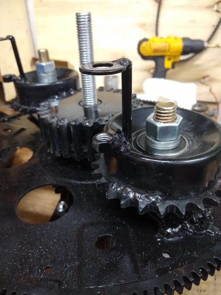
improved outer stops and “Halo” mounts after painting

Halo mount and improved outer stop as seen during setup

I have also improved the mounting (resembling a halo) for the swinging weight. This improvement also allows for the addition of strengthener braces if it is found to be necessary.

Halo Bracket for Swinging Weight

The new stops allow for actual adjustment of the stops. This will allow me to make small changes to stop position and find out if there is a particular “sweet spot” for the outer stop.

Improved outer stop and halo mount working well during SDC setup

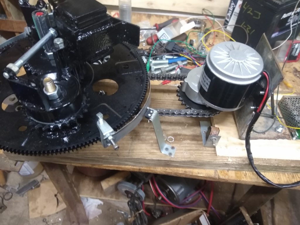
The CCW wheel is constructed to run on its own with its own separate motor and speed controller (as seen above). This is necessary to run the full gamut of necessary tests regarding phasing and RPMs. Once these tests are complete there will be better data regarding proper synchronization and whether the two opposing wheels should even be synched at all.

I have posted several videos on my YouTube and BitChute channels showing the building of the CCW and the new PIE 4.8 stops. Here (below) is the new PIE 4.8 CCW running its bench test with the SDC installed.

Here (below) is the first bench test run of the CCW before the SDC was installed.

Here (below) is the PIE 4.8 CCW set on some pipe rollers just to check for backward force (reversion) vs. forward force (thrust).

First Thrust bench Test of PIE 4.8 CCW Assembly

PIE 4.7 and “PIE X”

PIETECH 4.7 and “PIE X”:

It has been a while since my last post, or video so here is an update:

The PIE 4.7 second half (CCW wheel) is progressing, although somewhat slower than I would prefer as life’s circumstances have presented certain obstacles to its advancement. The first “dead blow” weight for it is ready to install, and another is in process.

I always said it is not a good idea to have more than one project going at a time, yet that is exactly what I am doing…

After communicating at length with other builders, I have split my time between the PIE 4.7 and a new design, the “PIE X”. It has some radically different internal components and will look a bit different but it is still what I would call a Pulsed Inertial Engine, so right now it is known as the “PIE X”.

This design has originated from other people so I will need their permission to “open source” any of that information! I require their permission to share or publish the information leading up to the PIE X without the consent of those who have been kind enough to share the basic design information with me!

If the PIE X is as feasible as predicted and becomes something worth pursuing more information may be provided (with permission), and if it falls short, I will provide thoughts regarding that failure (still, with permission only).

Note: The PIE X is quite a bit more expensive and much more complex to build and fabricate the components for, so it may not be something the casual hobbyist would feel comfortable with, at least not until there is a working prototype to prove the principals.

Those who know me and those who have followed along with my PIE/PIETECH projects know that I do not randomly spout “theory”. I only present factual information so until I have an experimental prototype, I would not request permission to elaborate any technical information. I only mention the PIE X as an ongoing project because it does slow the PIE 4.7 project and has pushed back the timetable to begin full testing. I am hoping to be performing “on road” testing of the PIE 4.7 by early June which gives me about 8 weeks.

I hope to be posting photos and videos VERY soon, so right now I need to go get busy, I have a PIE 4.7 to finish building and a PIE X to get underway!

Tolchin/Shipov Drives May Compliment PIE System

As the PIE project continues, I am not blind to reality. There are still many shortcomings to be overcome, forces within the PIE assembly which fight themselves and therefore fight against the very purpose of the PIE. “Reversion” is “anti-propulsion” and it is the bane of all inertial propulsion systems, a primary force to be circumvented as it cannot be eliminated. In the quest for circumvention there is a relatively simple sounding answer known as “redirection”. There is a type of device which has purported to have redirected reversion with good efficiency invented by a Russian named Tolchin and redesigned by another named Shipov. Because this Tolchin/Shipov (T/S) design effectively used redirection within a narrow band of geometric proportions, and because the mechanicals of the T/S drive are less complex than that of the PIE, I have allocated a bit of time and resource to verify T/S drive operation. Assuming the device is verified, a small T/S could be used as an anti-reversion device with the PIE and with other strong impulse drives as well.

Tolchin vs. Shipov: The Tolchin drive was originally fully mechanical with a spring motor and mechanical governors and brakes to build forward momentum and then partially nullify reversion. Once Shipov came into the picture the mechanical controls were replaced with electrical controls. I believe either would be effective, but electrical is easier to adjust and modify so that is the route my experimental work is following at this time.

Tolchin Drive
Shipov Drive

Noteworthy Difference: There is one other noteworthy difference! The Tolchin drive appears to have lacked the precision of the Shipov drive. Watching the videos of the Tolchin vs. the Shipov, Tolchin used one moveable mechanism inside another to lessen the reversion. The inside mechanism moved forward and back “pulling” the main trolly with what appear to be rubber bands. The inner mechanism may also be angled downward slightly to use gravity as an integral part of the cycle. Shipov eliminated these considerations with precise braking control of the rotating assembly.  

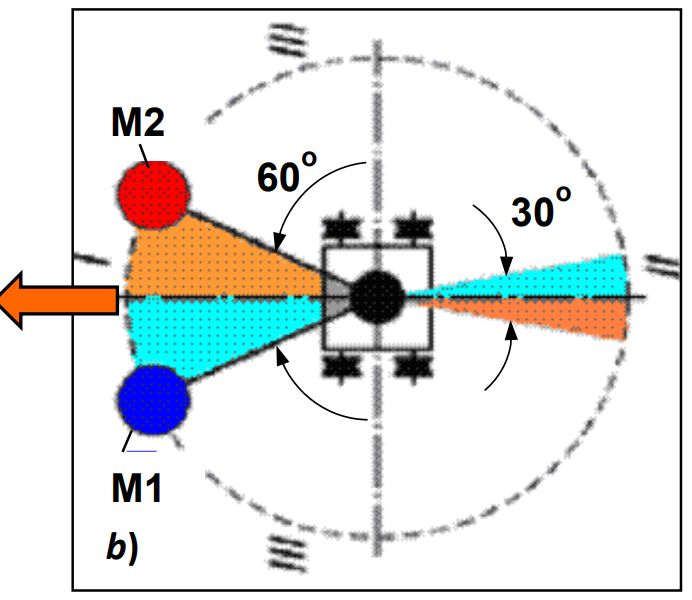
The Tolchin/Shipov drive cycle explained:

The T/S drive has 2 halves and they are identical mirror images of each other so I will only focus on 1/2 of the drive. I will be using clock positions of the weights for clarity. The rotation in this explanation will be clockwise to follow the numbers and 12 o’clock is straight forward.

1: At 12 the weight is moving at base speed.

2: At 1:30 (60 degrees) the weight is accelerated to approximately 2X to 3X the base speed (power stroke).

3: At 5:30 (30 degrees from center measured at the bottom) the weight returns to base speed.

4: The weight continues at base speed on around to 12 and starts over.

Since the acceleration force is designed to occur within a 90-degree arc (1/4 revolution), the forward thrust needs to be more than the reverse thrust used in returning the weights to the front. This is simple but stopping the acceleration (accelerated speed) at the exact right moment is critical if the T/S drive is to function!

Shipov Drive Cycle

Current: Right now, the gearing is put together and I am currently powering it with an obsolete cordless drill mechanism. Speed control is accomplished with the same controller being used on the PIE 4.7, including the SDC control.

Current T/S Type Drive Experiment

Problem: The problem with my replica is the weight’s return to base speed is not instant, and because the rotation is still moving too fast (and overshoots the desired slow-down position) the centripetal force pulls in the wrong direction. A brake is needed to quickly (instantly if possible) slow the rotation speed back to base speed. I believe this might be accomplished with a “motor brake” working similarly to a modern cordless drill which stops without coasting when the trigger is released. Another thought is that my weights are too heavy for the older model drill motor to effectively decelerate quickly, and they may need to be replaced with lighter weights.

Gyro, Centrifugal, Centripetal? Shipov called this a “4D gyroscope” where the 4th dimension is time (rotation speed), but it could also be called a “centripetal drive” since thrust is derived by accelerating the weights in an arc toward the rear, and then the centripetal energy is absorbed by reducing speed at the moment the direction is perpendicular to desired motion. Since the mirrored half is doing the same thing in the opposite direction, sideways force is cancelled at both the acceleration point and deceleration point.

PIE 4.7 – Now with Two Weights and Actuators, PIETECH P. 15

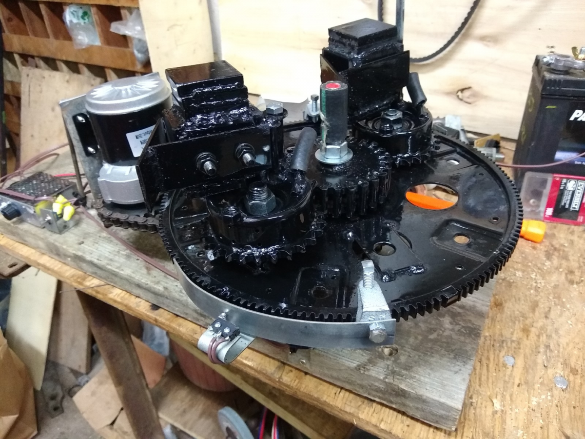
A second weight has now been put together for the PIE 4.7. It is .02kg heavier than the first weight, but that can be corrected (if necessary) by drilling shallow holes in the weight until corrected. The weight of each is 2kg +/-.

PIE 4.7 with Dual Weights and Actuators

Two SDC actuators are installed. They are each 8 inches long and are attached to the main wheel’s outer ring gear with ¼” beam clamps from the local hardware store.

New Controls

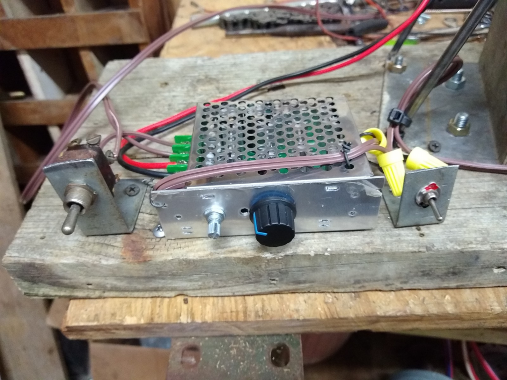
Additionally, the SDC potentiometer “pot” is installed next to the main speed control pot on the motor speed controller, a mini toggle switch was added to turn on or off the SDC function, and finally a main-power toggle switch was added between the battery and speed controller.

Bench testing is showing a most definite power output increase across the board when the SDC is on compared to tests without it. It seems that because of the improvements made, the PIE 4.7 (with its one wheel and two weights) is comparable to the PIE 2.1 which is twice its size. Proper testing will be done in the next week or so, then we will know for sure.

Fastened to the Bench & Back to Simple Chain Drive

A video is posted to both the YouTube and BitChute channels giving a quick tour of the PIE 4.7 and then a demo with it firmly attached to the bench.

Disassembled/Reassembled PIE 4.7 – Dual Actuator First Bench Test

PIETECH Page 13, PIE 4.6 Is Now PIE 4.7 With Addition Of A “DSC”

The integration of an external control circuit known as “Differential Speed Control” (or DSC) on the PIE 4.6 is such an important component that the PIE revision level is now PIE 4.7!

Micro Switch and Actuator for DSC

This latest test design is a “Differential Speed Control” (DSC) circuit added to the DC speed controller and actuated by a micro switch. When the micro switch is actuated via an adjustable cam the motor speed increases by an adjustable amount. The amount of increase is adjusted using a potentiometer (“pot”) using just 2 connections, effectively making it a rheostat or adjustable resistor. The pot and switch are in parallel with the adjustable pot on the motor speed controller, and simply lower the resistance in the control circuit of the motor controller.

Because the dc motor has more than enough power necessary to run the PIE, the speed change is nearly instant. The difference between the set speed and the higher speed is the “differential”, and this differential is acting in concert with the planetary gear set to effectively put more control over the weight’s velocity. It is the change of the weight’s velocity (including the changes when contacting the stops) which is responsible for the PIE’s propulsion!

I took a completely hand-held video (no tripod) of the new circuit in operation and it is now posted to YouTube and BitChute, the next video will be using the tripod.

The video can be seen here:

Page 14, Phase 2 – Outer Stops Cont…

April 14, 2020


The revised outer stop (os2) seems to be the most effective, however, it should be noted that it also puts the heaviest strain on the gears. The strain tends to change the timing of the sun gear(s). I am thinking that I should fasten the sun gear(s) to the axle shafts and change the axle shaft mountings to enable “on the fly” timing adjustments.
I have also added the stop tab (which contacts os2) to one of the 1” square weights. The result was a dramatic improvement over the original trials with that weight and I also had to add an extra stop tab to the 1” square to keep it from “backfiring” or spinning itself around to the wrong side of os2.
This all showed me that the os2 is really absorbing a tremendous amount of torque from the weight, and as the timing of the sun, planet and weight are becoming much more critical it is also having a harder time maintaining adjustment.
Note: After multiple, successful tests the forward thrust would suddenly be very diminished. Sometimes it would seem like the whole thing had been a joke on me & I would get very discouraged. 
This has been found to be the effect of the timing slowly slipping while test running. This illustrates the need for an improved locking mechanism for the sun gears, with an allowance for adjustment as needed.
 

Page 13, Phase 2 – Outer Stop

April 8, 2020

The outer weight stop is the device that stops the outer weight from swinging past the apex position of the planet gear. It stops the swing, absorbing the energy being imparted by the inertia of the weight, transferring that energy into forward motion and allowing the weight to stay at apex until it returns to the center of the sun gear and contacts the inner stop. The inner stop holds the weight until it is in position to be swung outward/forward where it contacts the outer stop again.
This illustrates how important the stops are and it begins to illustrate the stress imparted upon the gear teeth and the locks that keep the sun gears timed properly.
The outer stop seems to be where a large part of the stress is, so that is where I am concentrating my refinement efforts.
I have now tried several stops, and the 2 most successful will be called os1 and os2. Os1 is fastened directly to the planet gear and extends outward toward the weight where id stops the swing by contacting the weight’s connecting rod. Os2 is fastened to the planet gear but is inboard of the weight’s pivot. Os2 requires an extension coming from the inboard side of the weight’s pivot which contacts the stop. Intuitively, this seems to be a better idea. We shall see.

April 9, 2020

The outer stop version 2 (os2) seems to be much improved over os1 and I have changed 2 planet gears to utilize this improved design.

One of the (hopefully) benefits of this design is a change in the timing which directs much more of the generated force toward the forward direction. So much so, that I “might” be able to eliminate the counter rotating assembly. If I can, this will greatly improve efficiency!! I am hopeful.