Trammel Update for mid-March 2023

3/10/2023

Whew… It has been a really busy 4 months since I posted here! So here is a “snapshot update” of the highlights followed by videos.

  1. Nov. 2022: The PIE 5.0 works. No where near as well as I wanted, but one more time I learned sooo much that I call it a win!
  2. Dec. 2022: I took what I learned and applied it to the Trammel engine.
  3. Dec. 2022: The AMP, or “Active Mass Point”, design is put into service. “Game changer”!!!
  4. Jan. 2023: New years day, the Trammel displays repeatable “proof of principal” thrust!
  5. Feb. 2023: Partial overhaul of the Trammel. Several weak points proved where many of the mechanical stresses are and where they are not.
  6. Feb. 2023: Built a new balance beam with a 20:1 ratio. The Trammel again displays repeatable thrust.
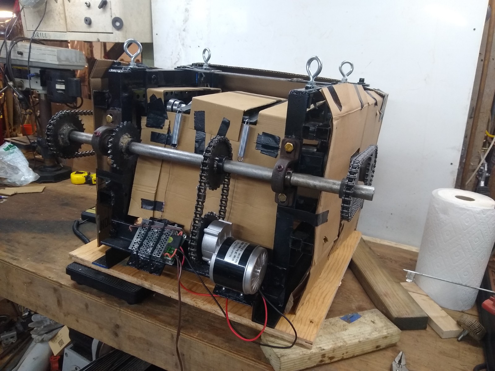
  7. Mar. 2023: The special ordered brushless motor gives out & looses so much power it is affecting thrust output.
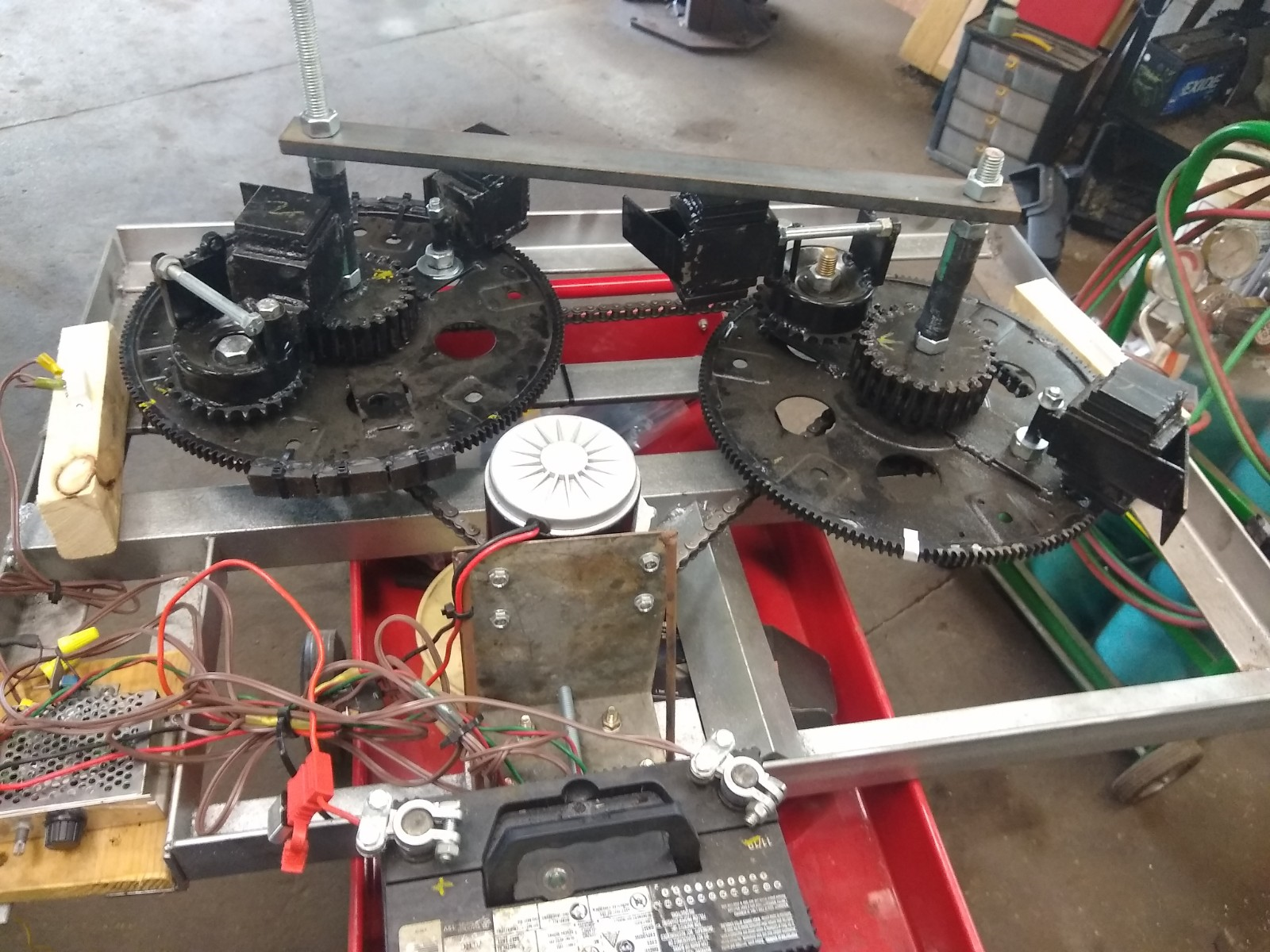
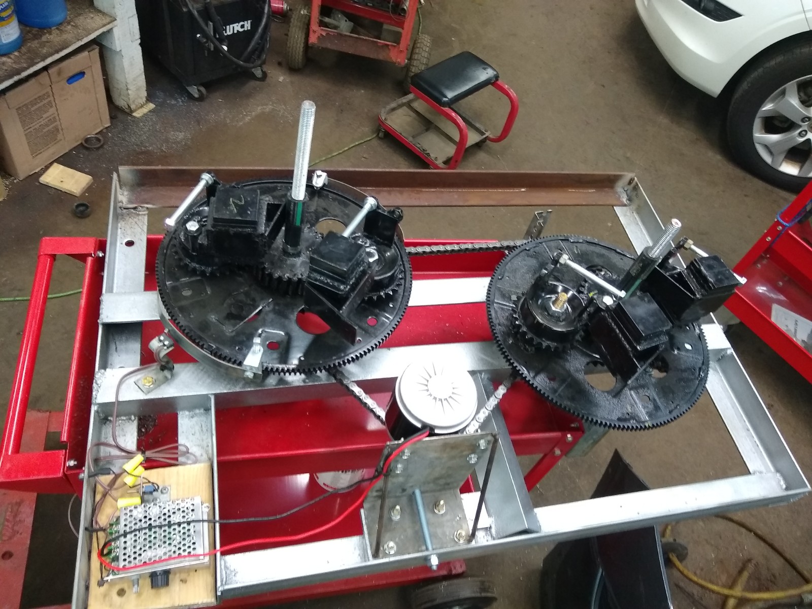
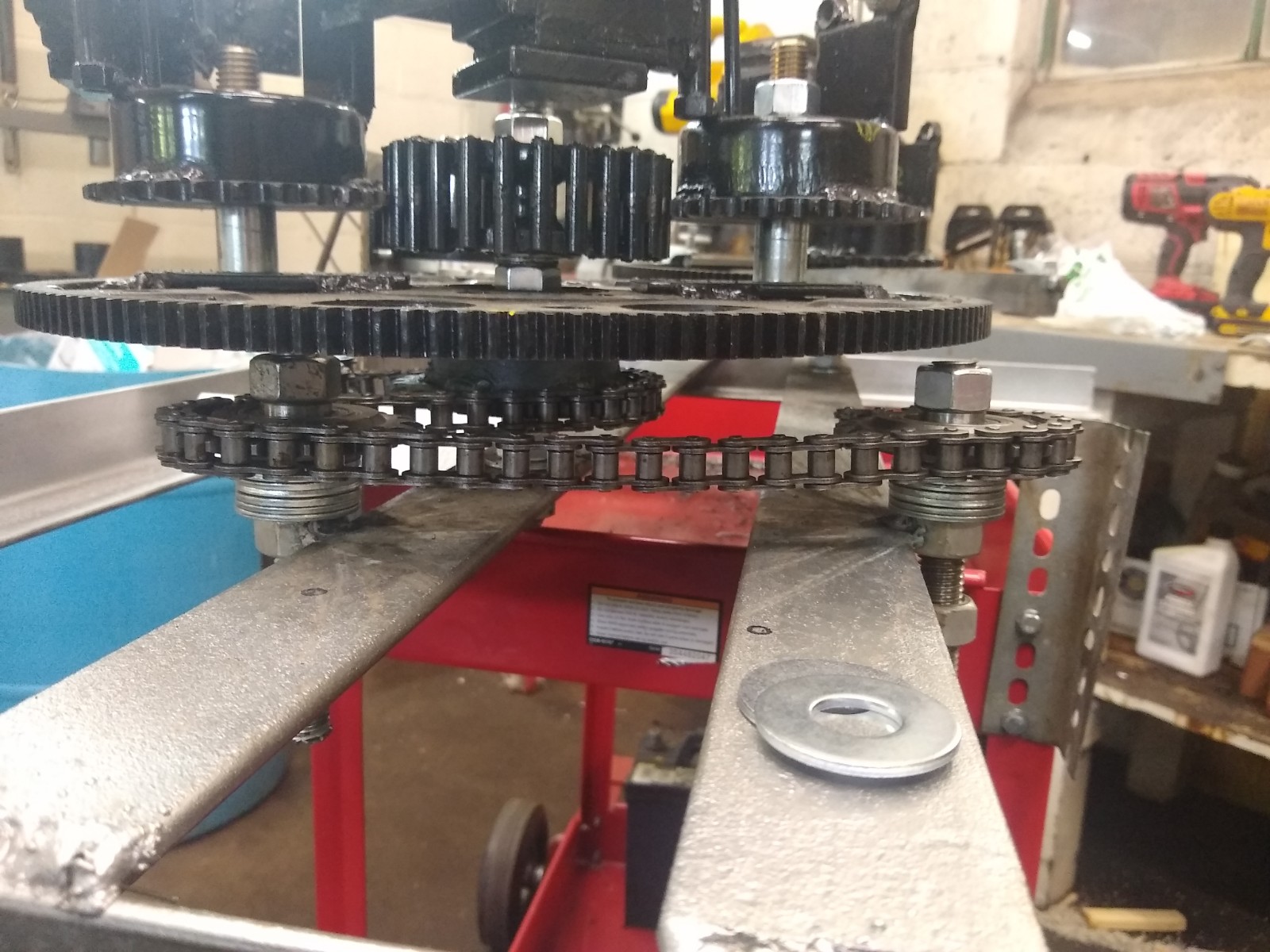
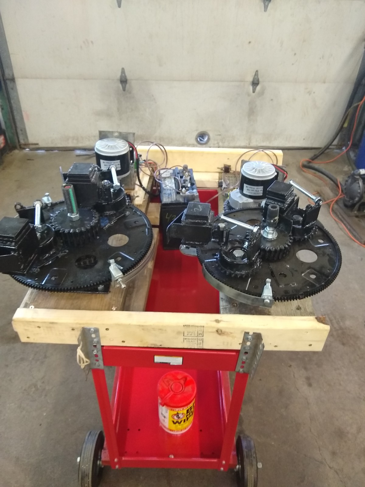
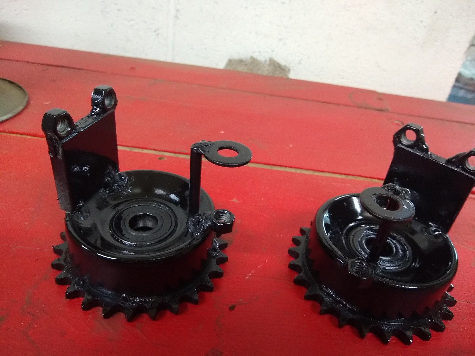
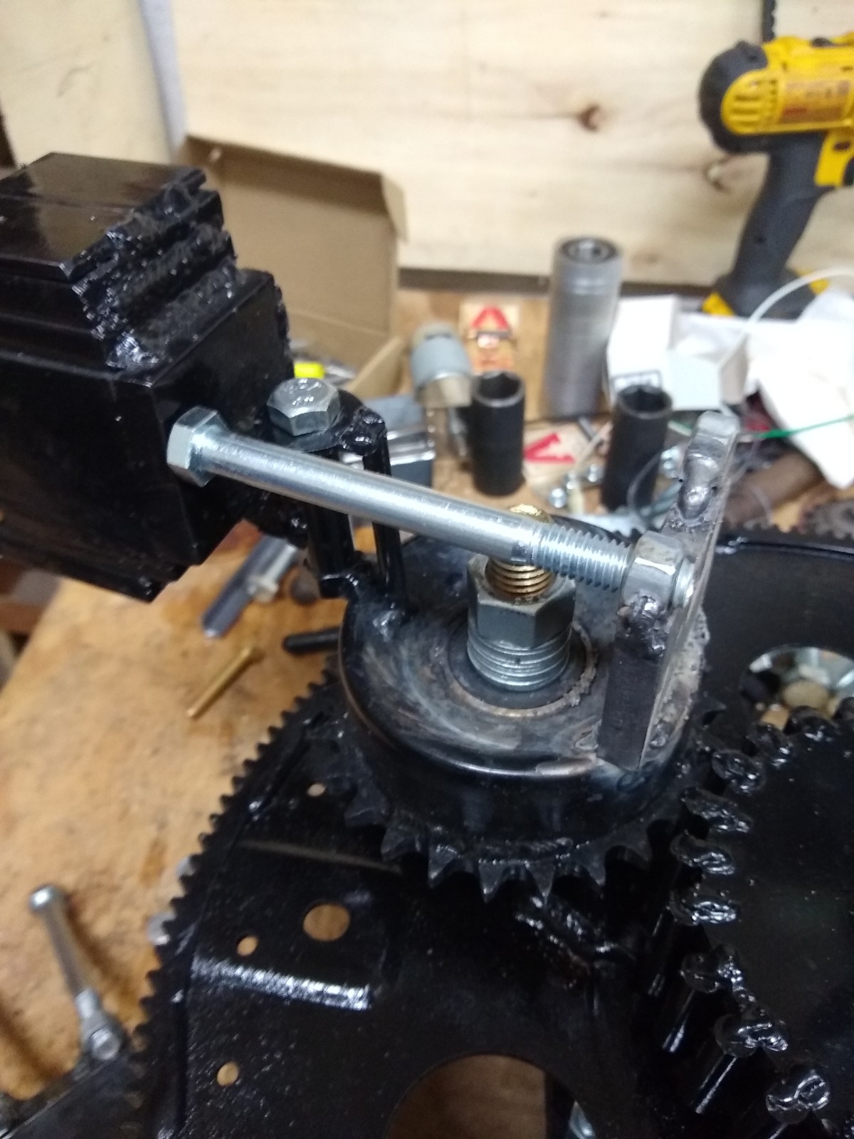
  8. Mar. 2023: Revamped the motor drive and installed 2 identical 24 volt motors with a 1:2 overdrive gear ratio.
  9. Mar. 2023: Theory of  “mass displacement” is better understood.

Like I said, I have been busy! Here are some of these highlights on my YouTube channel and mirrored on my Bit Chute channel.

PIE 5.0
Thrust!
Repairs & partial overhaul complete & still has thrust!
Thrust demo on new balance beam
Two motors at full speed

So next up will be back to the balance beam and we will be making adjustments to improve thrust. In the near future, an improved build is on the docket using everything learned thus far including improved versions of the highly successful AMP design.

I can easily speculate that the Trammel Engine will become more compact but much stronger within a protective enclosure that will also reduce the noise level dramatically.

Stay tuned for more!

Trammel Testing, APEC, PIE Mini

It has been MONTHS since I updated here… A lot has happened in my life and in the shop! For those interested, I have switched gears in my professional life. Since the change is quite dramatic, I have been under some stress “getting in the groove”, but it is a needed change and I’m getting it all figured out.

The PIE X aka Trammel Engine is coming along. Inside it (still not ready to reveal too many details) are some components which were made too weak, but they have been rebuilt and replaced with much more robust pieces! I have experienced some intermittent thrust and have kept moving forward with this as much as possible. I also recently received a much-improved motor and speed controller which is now installed.

A Look at the New Motor
First Run Test

It has become quite evident that as I contact potential business partners and investors, I need a small and lightweight demonstration model which can be taken along to those meetings. With that in mind, I introduce the “PIE Mini”. The PIE Mini is a nearly complete, single weight, working, demo model which is really small and light with plastic gears and a hollow tube instead of a large “wheel”. It’s power source is a super cheap cordless screwdriver from Harbor Freight. Although it is intended to be a portable demonstration device.

I believe it will also be a design which could become the first model of a sellable working model for science minded people everywhere to experiment with.

There are a couple of videos of the PIE Mini on BitChute .

First Test on Wheels

I have also now run a live demo of the Mini at the APEC conference on Feb. 27, 2022. During this presentation I showed that the unit actually needs mass to operate and that is really it’s only environmental prerequisite. I should be posting that presentation on my BitChute and YouTube channels very soon. Until then, here is a link to it on the American Antigravity YouTube channel.

Part 1
Part 2

I want to thank Ross Small for joining the video conference with a presentation of his own. He is building a “linear thrust” machine in the hopes that it will be a helpful learning aid for everyone to better understand the mechanism of inertial propulsion. Some of those very principals are integral to the Trammel Engine, and have also got me thinking about other, future, design builds.

Ross Small’s Presentation Part 1
Ross Small’s Presentation Part 2

PIE X Gets a New Name – “The Trammel Engine”

November was a very busy month for Stclairtech R&D, and for the PIE X project!  

Ready For “Public” Testing

So much has been accomplished with the PIE X project it is mind boggling!!! The “backfire” issue has been resolved and there have been some very successful tests completed running with the electric motor.

Some of the highlights are:

The “backfire” problem is now well controlled with a minor design workaround. Future builds will take these backfire control requirements into account so that “workarounds” will be unnecessary.

The PIE X has earned itself a name of its own and is now known as the “Trammel Engine”. It is a name which is both literal and figurative. Literal because it has internals which resemble the operation of an ellipsograph, or “Trammel of Archimedes”, and is a figurative tongue-in-cheek reference to the same machine’s moniker of being a “do-nothing machine” since its purpose seemed nonsensical for the most part.

 The Trammel Engine (T-Engine or TE for short) is now running well enough to perform some rudimentary testing which has demonstrated true linear thrust. It has been measured thrusting upward with a weight scale with an averaged thrust of .7 lbs. and peaks ten-times that amount running at input speeds of no more than 350 RPM.

Unlike the earlier PIE systems based on Thornson technology the T-Engine does not seem to have a low-speed limitation, and it is creating more thrust as RPMs increase.

A few shareable facts (so far):

1- The TE has externally driven mechanical components which are driven via the electric motor(s) and cause overall rotation along with internal rotating components.

2- There are 3 major rotating component assemblies consisting of metal parts using ball-bearings for friction reduction.

3- Some of the pieces of the internal assemblies can be labeled with names resembling those of internal combustion engines. Pistons, connecting rods, camshaft-like parts, and flywheels are just some of those named components.

Overly simplistically stated, it uses something very similar in function to a lever pulling a load which is allowed to move past apex and “snap over center”. This over center, snapping, rotating assembly is moving masses, accelerating, decelerating, and recovering them 4 times per disc rotation.

The internal timing of these components, and the use of a “camshaft-like” sub-assembly is of utmost importance to eliminating the backfire issue!

There are several videos available on YouTube and BitChute, the latest of them (at this writing) is a 2-part set called “Trammel Engine Works Part 1” and “…Part 2”. Part one shows the test rig, and part two shows a “successful” test which ended abruptly when the fuse blew. It turned out that the fuse blew because one of the “connecting rods” broke. Here are those videos below.

Part 1
Part 2

The broken and damaged parts are now being replaced and repaired, there will be more tests to come very soon! And hopefully more can be revealed soon…

PIE X Being Built Now

I am still around! I am still building! I am not going anywhere!

It has been quite a while since my last posting and my last video. I have been hard at work on the PIE X design. I am still not at liberty to detail its design except to say it is based on a series of rotating discs which use specialized components under tension and using a “Mass Displacement” system should create efficient linear thrust. It is still being called a PIE because it does have a pulsed propulsion component, but these pulses “should” happen 4 times per revolution and run at 1000 RPMs or more so the pulsing should be MUCH smoother than that of the previous PIEs.

Although this is not my original design, and it has been done before, there are no working devices known to exist and its duplication attempts have all been in vain… Until now. Well, soon anyway! The main unit is framed up and the rotating discs do rotate very well. The specialized internals are partially complete, and testing has had some very positive results thus far!

Without giving details regarding the origin of this base design, the person who originated it stated that they ‘…will not give away all my secrets…” and emphatically stated that others will have to “…figure it out for themselves…” and so we are figuring it out now.

It is unfortunate that the original designer was (and still is) compelled to distance themselves from this technology!

What I can say about the PIE X is that it is using 3 rotating “wheels” which are referred to as “discs” or “plates” and has at least 10 times more parts as the PIE 4.x series has in it, not including nuts and bolts holding the framework together. I can also say that I have built it with absolutely no regard for overall weight. Most of the unit is built with heavy steel components rather than lighter weight aluminum and/or hollow parts. Overall weight has become too much to easily move around as it is well over 130 lbs. and still does not have an electric motor installed. I am hoping that with all the excess mass it has enough thrust to easily demonstrate linear thrust.

Right now I am turning it with a hand crank, and because of a problem with what I refer to as a “backfire” I will not be installing a motor until later. The backfire is 100% mechanical (no actual fire) and refers to a point internally where stresses are suddenly released in the wrong direction and a backward movement happens (inside). This could have catastrophic effects, so the issue needs resolution before a motor can be used!

I did post a rather ambiguous video online with the internal pieces covered (for now)…

First Public Look at the PIE X

PIE 4.8 Re-Phased and then Switching to Co-Rotating Design Testing (2 Updates)

On 7/31/2021 the counter rotating PIE 4.8 was re-phased to have the planet gears synchronized (self-propulsion mode) but then one plant gear was removed from each wheel so that forward pulses will alternate from on side to the other. The non-functioning weights were fastened to the planet gear mounting holes to help balance the wheels a bit.

Results were very similar to having all the planet gears and weights in place and operational with road testing showing a 4% to 6% reduction of engine load at the standard speed of 55 MPH with little to no headwind.

I believe this poor performance may be due to the counter-rotating wheels. Previous testing has shown better thrust using co-rotational wheels (rotating in the same direction). It has been suggested that counter rotation might be needed for stability, especially in either an air or space (aerospace) vehicle, but co-rotation should be very possible with proper management using either air foils or gyroscopes. Co-rotation should still be quite manageable a with minimum amount of manipulation.

8/10/2021 Update

I have now rerouted the chain on the PIE 4.8 so now the Left and Right wheels both turn clockwise, and I have modified the ramp on one of the RH wheel’s weights for the direction change and timed the wheels for self-propulsion (synchronized). With just one weight on the right wheel and two weights on the left wheel I now see that it is a definite improvement over the counter rotating wheel setup!

The first noticeable difference between counter rotating and co-rotating is when counter rotating in this same configuration of 2 weights on left and one on the right the propulsion pulse was strong when a single weight pulsed and weak when two weights synchronously pulsed. With co-rotating wheels the propulsion pulse is strong when a single weight pulsed and doubles in strength when two weights pulse synchronously. In simple terms, the unit is stronger when co-rotational!

I need to put trolley wheels under it again to test properly on the bench, but the unit seems strong and is pulling itself (sliding forward) across the bench when running even without fine tuning the gear timing. Next, I will adjust the gear timing and modify the other weight for clockwise rotation so that I can complete this round of testing.

If there was lots of extra time to do extensive testing it would be best to build it with 4 wheels, two co-rotating and two countering them to be able to arrange them in different ways to record and study the results. I don’t feel it is necessary at this time as the testing I have done is more than adequate to demonstrate the workability of the PIE system.

I have discussed the origin of the SDC and the subsequent positive effects of its use, and when I was setting up the PIE 4.8 to co-rotate, I could visually see the point of heavier motor load in the PIE’s rotation. So I published a short video of this visually obvious effect demonstrating the position in rotation which needs the RPM boost using the Speed Differential Control (below).

More to come soon!!!

PIE 4.8 Nearly Ready for Road Testing:

Over the last few weeks, a lot of progress has been made!

The PIE 4.8 CW & CCW halves have been assembled and tested.

 Testing has been done with both running on separate motors at both similar and different speeds, with the conclusion that the halves need to be synchronized to be effective.

A test cart has been constructed with smooth runners to see if the PIE and its wheels were pushing against the wheels’ friction in any way which would indicate a stick-slip drive. Results show that the PIE 4.8 would cleanly self-propel off of the cart under it (which moves as easily as the PIE) without either pushing the cart back or pulling it along. There are those who say that “it proves nothing”, to which I say “OK… I really don’t care! I am not trying to “prove” it works”.

I have a video of that test here:

A new frame has now been constructed for the dual PIE 4.8 and the assembly is almost ready for full-on road testing.

PIE 4.8 frame being assembled

A chain drive was devised to rotate the wheels in opposite directions from a single motor, and the SDC only needs to be connected to one wheel for operation. The frame is pretty heavy being made from 2” X 2” X 3/16” steel angle, but it should not “flex” at all during operation!

PIE 4.8 Chain

Here is a video of the PIE 4.8 being tested on its new frame:

I have also been asked to do a presentation for the APEC conference. I am putting a Power Point (PP) presentation together at this time which I will narrate live rather than pre-recording. There will be graphics (some of which were supplied by Mr. Tokio Muramatsu) and a short “timeline” video… What else is yet to be determined.

More to come as soon as possible!

PIE 4.8 Testing- and -Doubters, Debunkers, and Haters:

Well now, it seems that with the openness of the experimentation, building, fabricating, and functional videos that the “it doesn’t work” folks have become “it only works because of” folks.

The better we get this working, and the more verified data there is, the more people keep coming up with reasons they think we get propulsion. Primarily this presumptive opinion input has revolved around friction. The common theory is that “contact” with virtually anything is the friction causing propulsion. I cannot say that anything is impossible, but short of tossing this thing out into space it will be nearly impossible to “disprove” that theory! Here is my position on this… “Who freaking cares?!?!?!” It just works, so let us expand on this and put it to use for the betterment of EVERYONE!

I get it that the super smart technical theorists believe that anything that isn’t incredibly complex simply cannot work. Sorry people, but that is just another false theory which has been mistaken as fact.

Mine is NOT the only system that works, mine is not the only tech that needs to be openly replicated. If the replications are done with an expectation of failure, it will most likely fail. If they are done with an open & optimistic attitude with an expectation of recording valuable data, extraordinary things are possible!

PIE 4.8 First Test Setup

I have recently published the video on YouTube and BitChute of the first round of Dual-Wheeled testing with fully independent asynchronous control of each wheel (CW & CCW rotating). More testing videos will be published, and a comprehensive report will be published when these tests are complete. That video is visible below.

PIE 4.7 is now the PIE 4.8 with Thrust Test Video

The PIE counterclockwise wheel (CCW) is nearly finished and will be tested very soon. I made a significant change to the “outer stop” which works so well to warrant changing up the model number to PIE 4.8 and I am installing them on all of the planet gears for the PIE 4.8.

improved outer stops and “Halo” mounts after painting

Halo mount and improved outer stop as seen during setup

I have also improved the mounting (resembling a halo) for the swinging weight. This improvement also allows for the addition of strengthener braces if it is found to be necessary.

Halo Bracket for Swinging Weight

The new stops allow for actual adjustment of the stops. This will allow me to make small changes to stop position and find out if there is a particular “sweet spot” for the outer stop.

Improved outer stop and halo mount working well during SDC setup

The CCW wheel is constructed to run on its own with its own separate motor and speed controller (as seen above). This is necessary to run the full gamut of necessary tests regarding phasing and RPMs. Once these tests are complete there will be better data regarding proper synchronization and whether the two opposing wheels should even be synched at all.

I have posted several videos on my YouTube and BitChute channels showing the building of the CCW and the new PIE 4.8 stops. Here (below) is the new PIE 4.8 CCW running its bench test with the SDC installed.

Here (below) is the first bench test run of the CCW before the SDC was installed.

Here (below) is the PIE 4.8 CCW set on some pipe rollers just to check for backward force (reversion) vs. forward force (thrust).

First Thrust bench Test of PIE 4.8 CCW Assembly

Tolchin/Shipov Drives May Compliment PIE System

As the PIE project continues, I am not blind to reality. There are still many shortcomings to be overcome, forces within the PIE assembly which fight themselves and therefore fight against the very purpose of the PIE. “Reversion” is “anti-propulsion” and it is the bane of all inertial propulsion systems, a primary force to be circumvented as it cannot be eliminated. In the quest for circumvention there is a relatively simple sounding answer known as “redirection”. There is a type of device which has purported to have redirected reversion with good efficiency invented by a Russian named Tolchin and redesigned by another named Shipov. Because this Tolchin/Shipov (T/S) design effectively used redirection within a narrow band of geometric proportions, and because the mechanicals of the T/S drive are less complex than that of the PIE, I have allocated a bit of time and resource to verify T/S drive operation. Assuming the device is verified, a small T/S could be used as an anti-reversion device with the PIE and with other strong impulse drives as well.

Tolchin vs. Shipov: The Tolchin drive was originally fully mechanical with a spring motor and mechanical governors and brakes to build forward momentum and then partially nullify reversion. Once Shipov came into the picture the mechanical controls were replaced with electrical controls. I believe either would be effective, but electrical is easier to adjust and modify so that is the route my experimental work is following at this time.

Tolchin Drive
Shipov Drive

Noteworthy Difference: There is one other noteworthy difference! The Tolchin drive appears to have lacked the precision of the Shipov drive. Watching the videos of the Tolchin vs. the Shipov, Tolchin used one moveable mechanism inside another to lessen the reversion. The inside mechanism moved forward and back “pulling” the main trolly with what appear to be rubber bands. The inner mechanism may also be angled downward slightly to use gravity as an integral part of the cycle. Shipov eliminated these considerations with precise braking control of the rotating assembly.  

The Tolchin/Shipov drive cycle explained:

The T/S drive has 2 halves and they are identical mirror images of each other so I will only focus on 1/2 of the drive. I will be using clock positions of the weights for clarity. The rotation in this explanation will be clockwise to follow the numbers and 12 o’clock is straight forward.

1: At 12 the weight is moving at base speed.

2: At 1:30 (60 degrees) the weight is accelerated to approximately 2X to 3X the base speed (power stroke).

3: At 5:30 (30 degrees from center measured at the bottom) the weight returns to base speed.

4: The weight continues at base speed on around to 12 and starts over.

Since the acceleration force is designed to occur within a 90-degree arc (1/4 revolution), the forward thrust needs to be more than the reverse thrust used in returning the weights to the front. This is simple but stopping the acceleration (accelerated speed) at the exact right moment is critical if the T/S drive is to function!

Shipov Drive Cycle

Current: Right now, the gearing is put together and I am currently powering it with an obsolete cordless drill mechanism. Speed control is accomplished with the same controller being used on the PIE 4.7, including the SDC control.

Current T/S Type Drive Experiment

Problem: The problem with my replica is the weight’s return to base speed is not instant, and because the rotation is still moving too fast (and overshoots the desired slow-down position) the centripetal force pulls in the wrong direction. A brake is needed to quickly (instantly if possible) slow the rotation speed back to base speed. I believe this might be accomplished with a “motor brake” working similarly to a modern cordless drill which stops without coasting when the trigger is released. Another thought is that my weights are too heavy for the older model drill motor to effectively decelerate quickly, and they may need to be replaced with lighter weights.

Gyro, Centrifugal, Centripetal? Shipov called this a “4D gyroscope” where the 4th dimension is time (rotation speed), but it could also be called a “centripetal drive” since thrust is derived by accelerating the weights in an arc toward the rear, and then the centripetal energy is absorbed by reducing speed at the moment the direction is perpendicular to desired motion. Since the mirrored half is doing the same thing in the opposite direction, sideways force is cancelled at both the acceleration point and deceleration point.

PIE 4.7, Testing & Neg. Comments, PIETECH P.15

The last round of single-wheel PIE 4.7 testing is done and the video has been posted. I videoed the testing in multiple “takes” due to time constraints. There are more videos that “could” have been taken, but I chose to forgo the videoing of tests with little or no result differences (I get too long-winded as it is).

There have been some video comments stating in various ways that because it is not a fully successful propulsion engine, that the project should be scrapped, and I should re-focus my energy into more conventional technologies… Everyone is entitled to their opinions. I suppose I could easily get indignant and respond with an expression reflecting that inflamed “knee jerk” emotional response, but there is no point. If watchers do not like what they see, there are plenty of other things to watch so apparently there was enough interest to post a public comment.

I created a post a few days ago, but I have not posted it, primarily because of what is some passive-aggressive contact from a handful of people. I have decided not to let this discourage the public furthering of the PIE project and that post is included in its entirety and without editing after this one, posted as its own post as was originally intended.

Note: I am, from now on, choosing to link and embed videos from BitChute (and maybe others too) rather than YouTube. With the censorship being displayed at YouTube, how long will it be before my videos are labeled as something needing censorship too?

PIE 4.7 Single Wheel With Multiple Configurations