PIE 7 Update:
These have been very busy months for me since my last post, I certainly didn’t intend for it to be so long between posts.
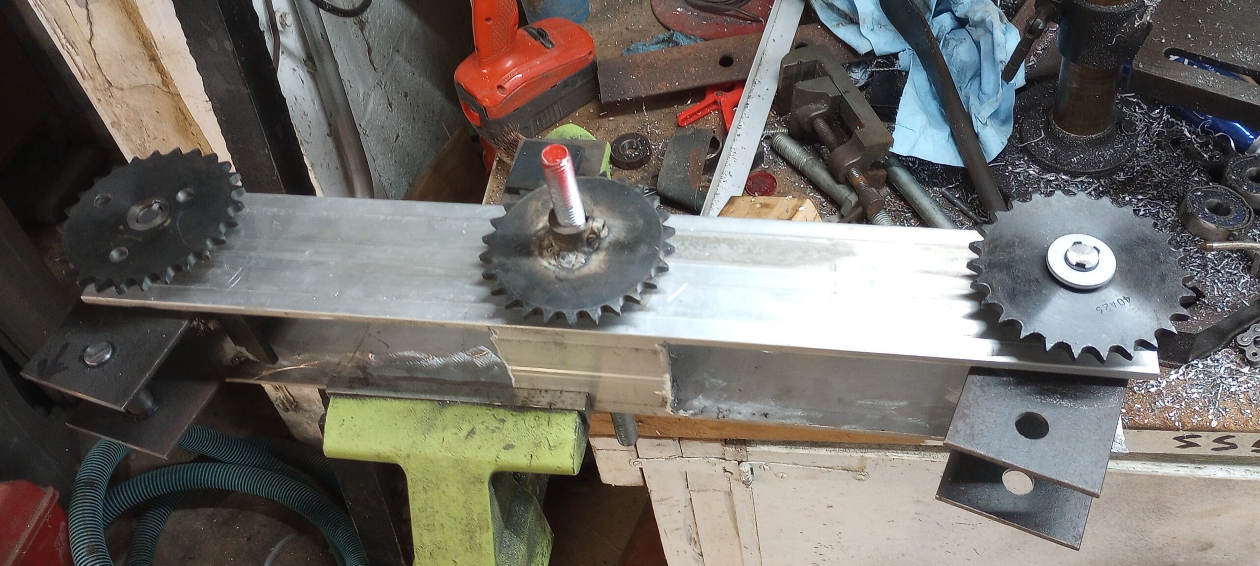
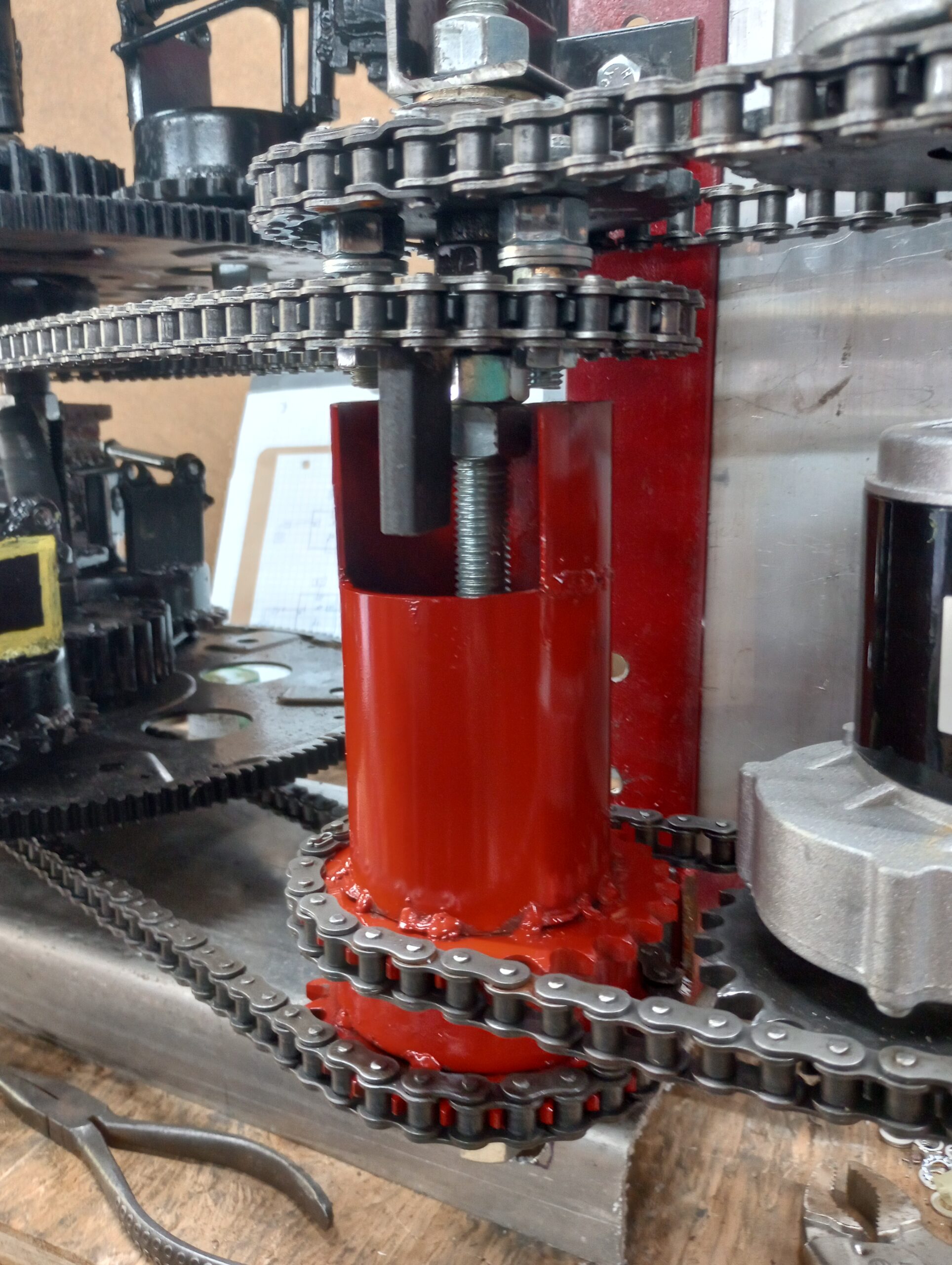
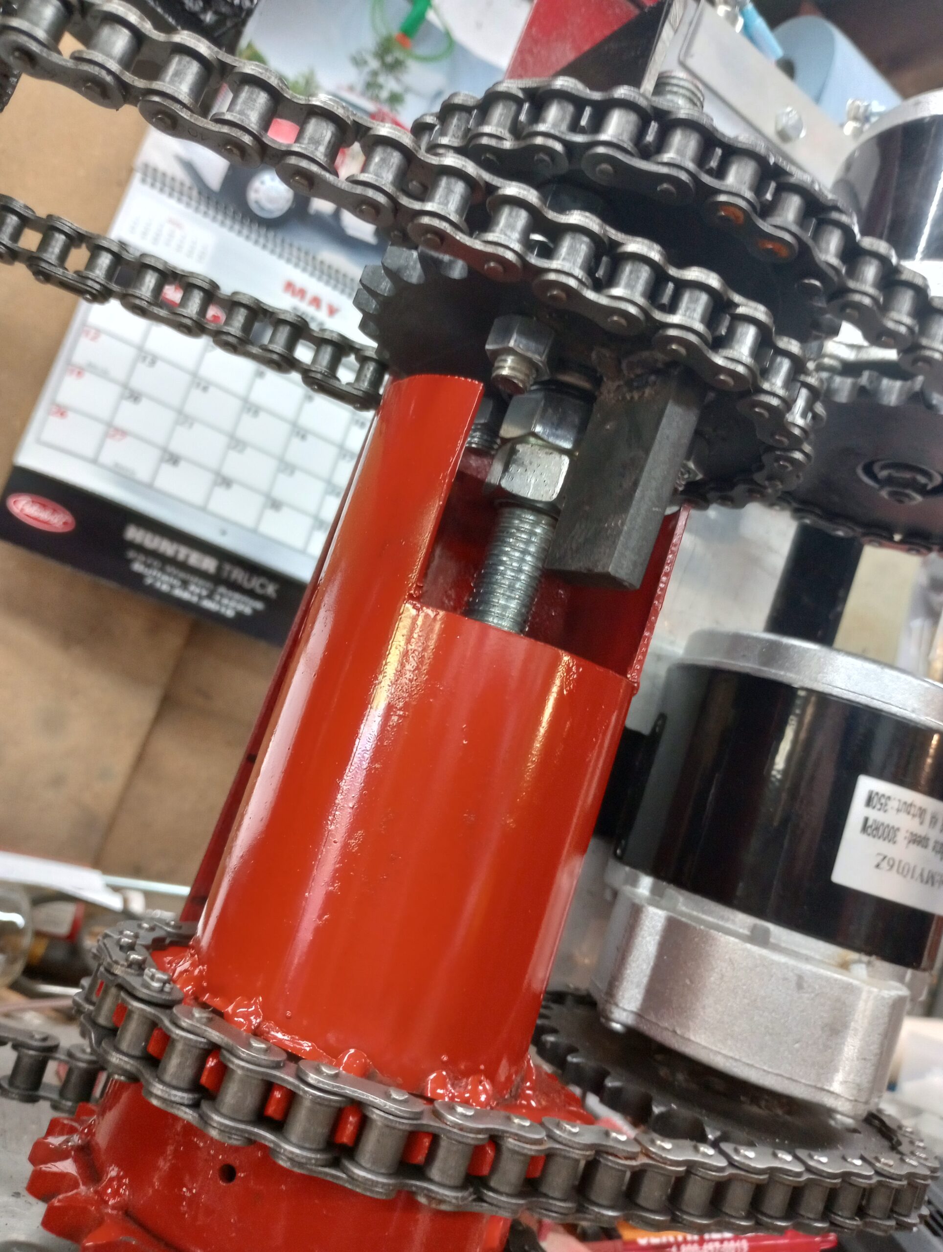
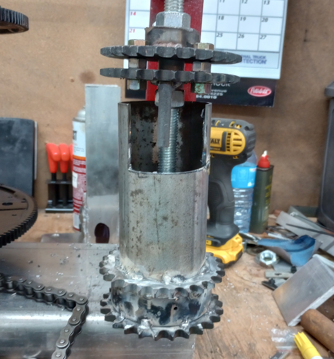
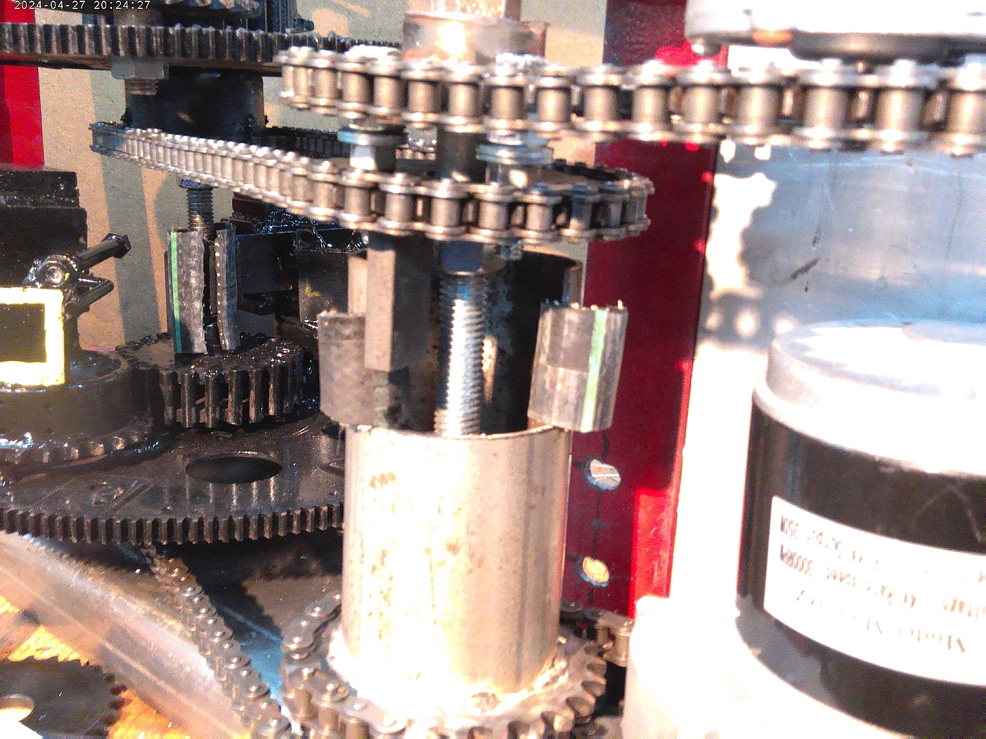
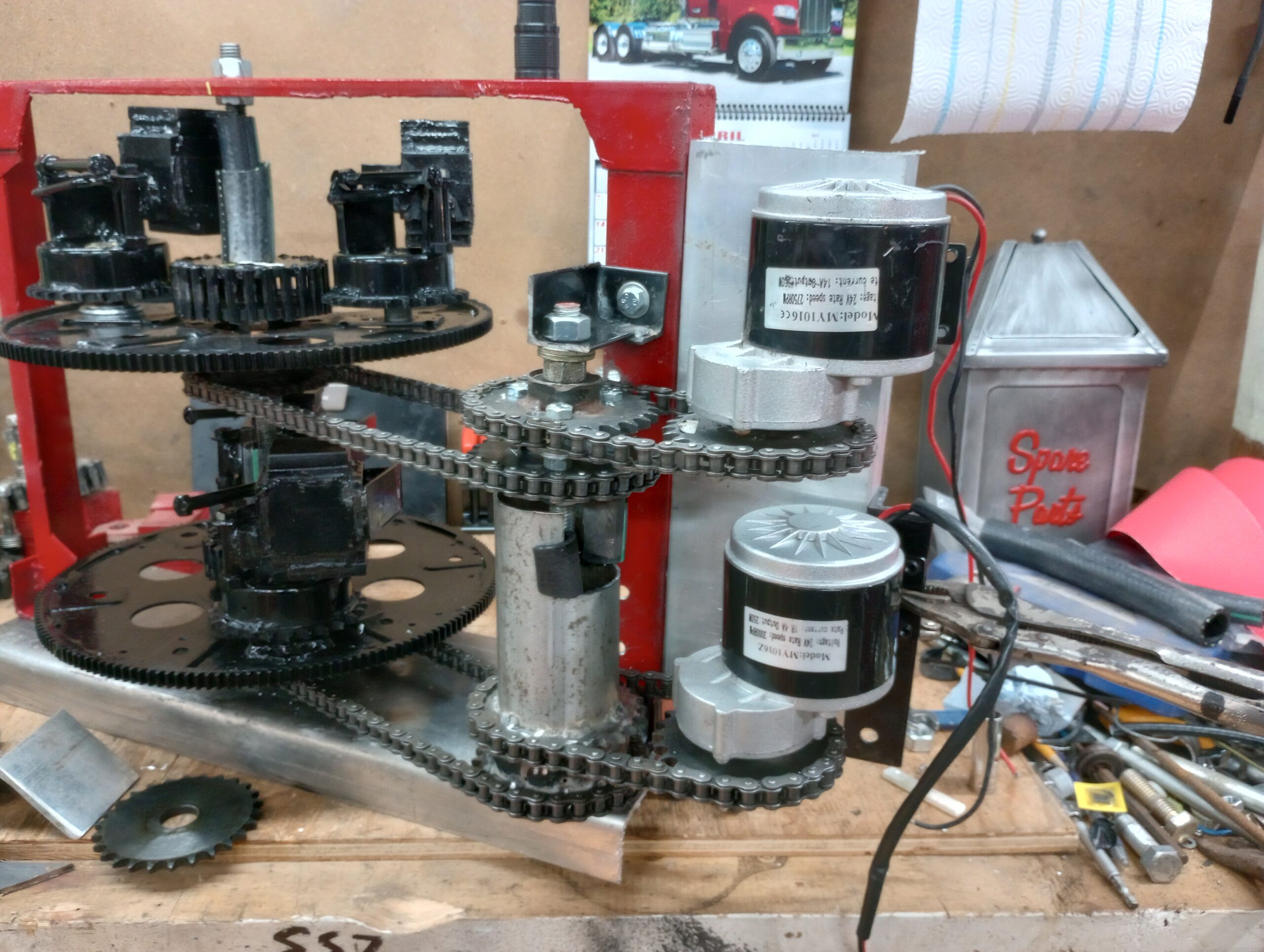
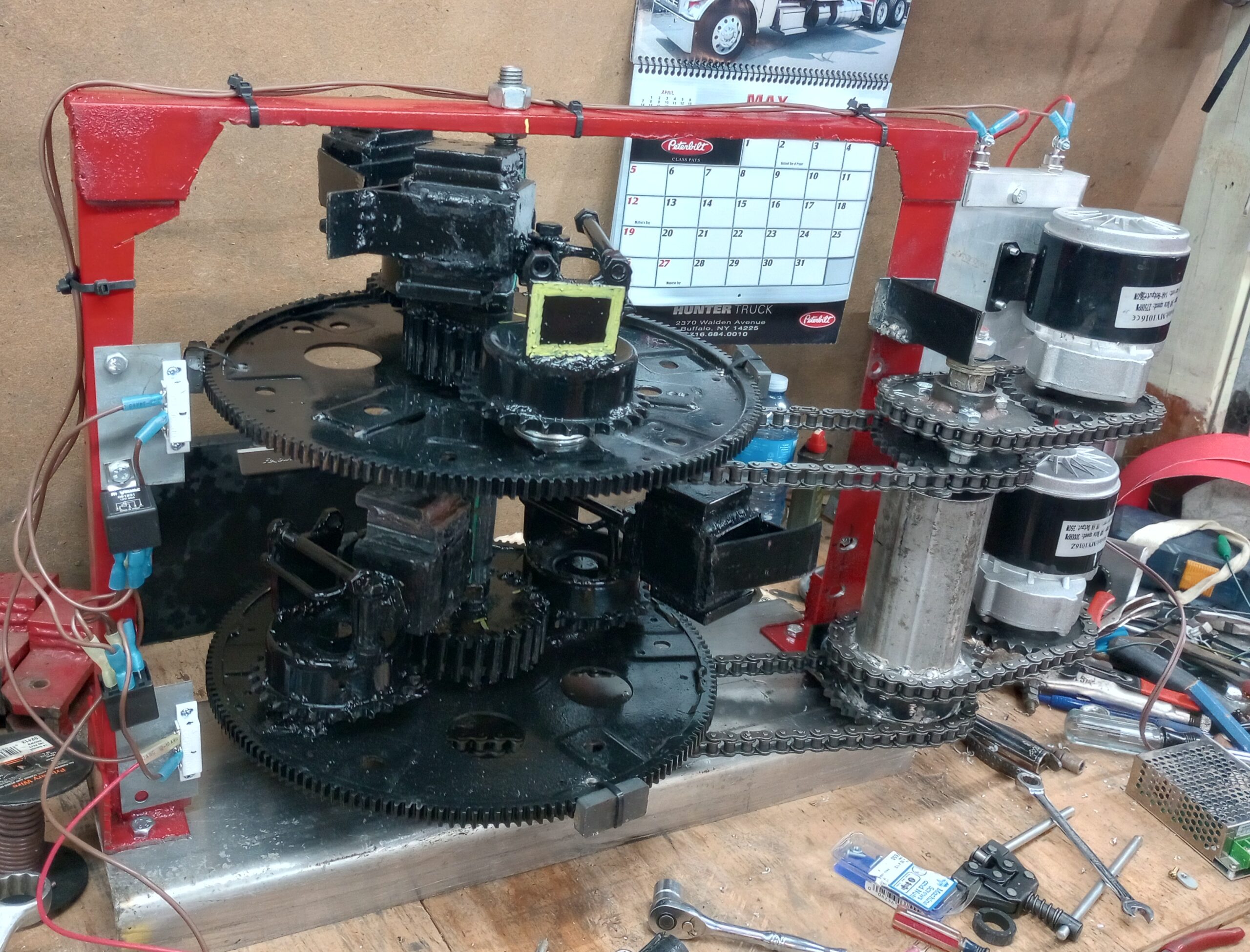
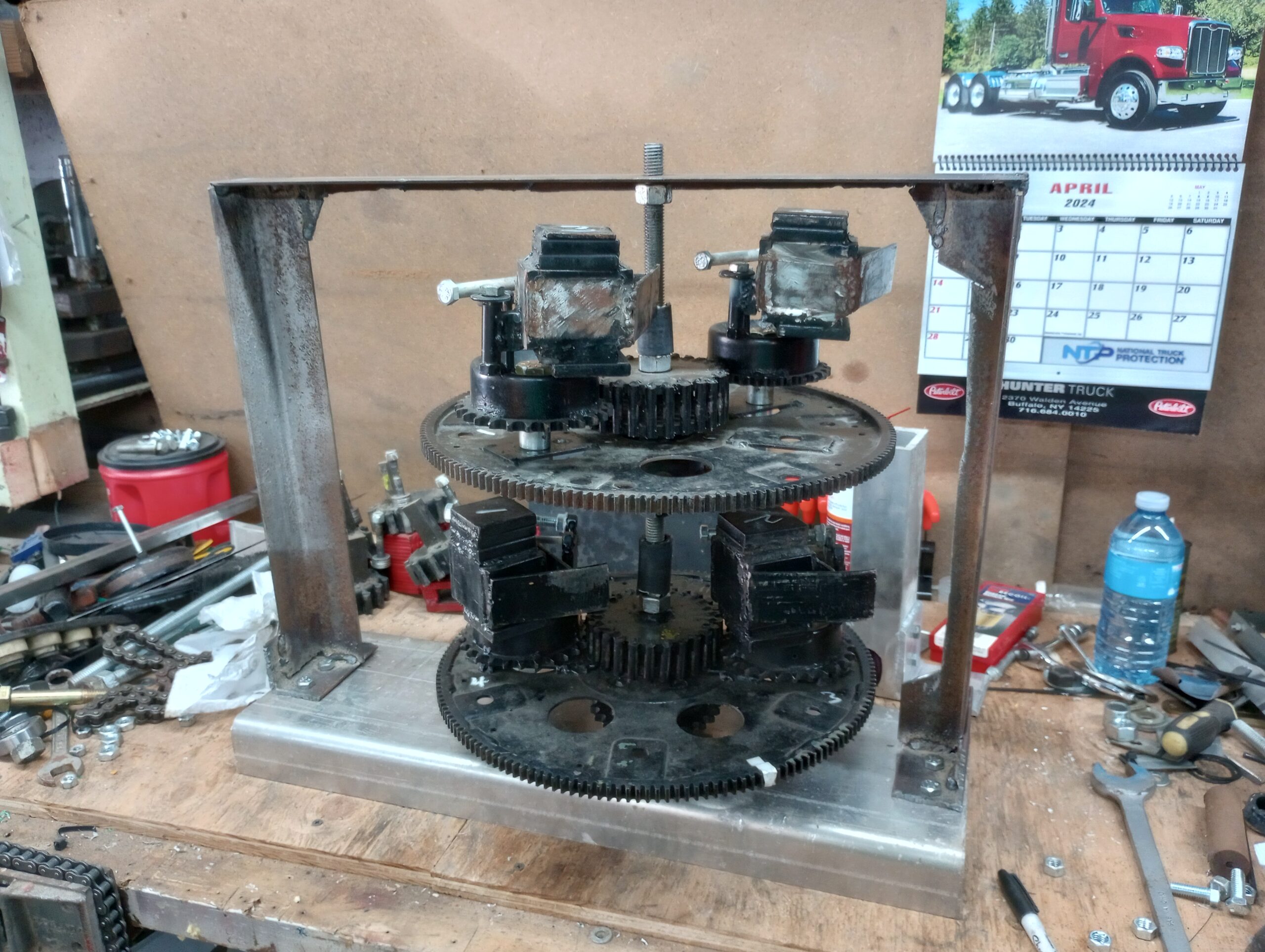
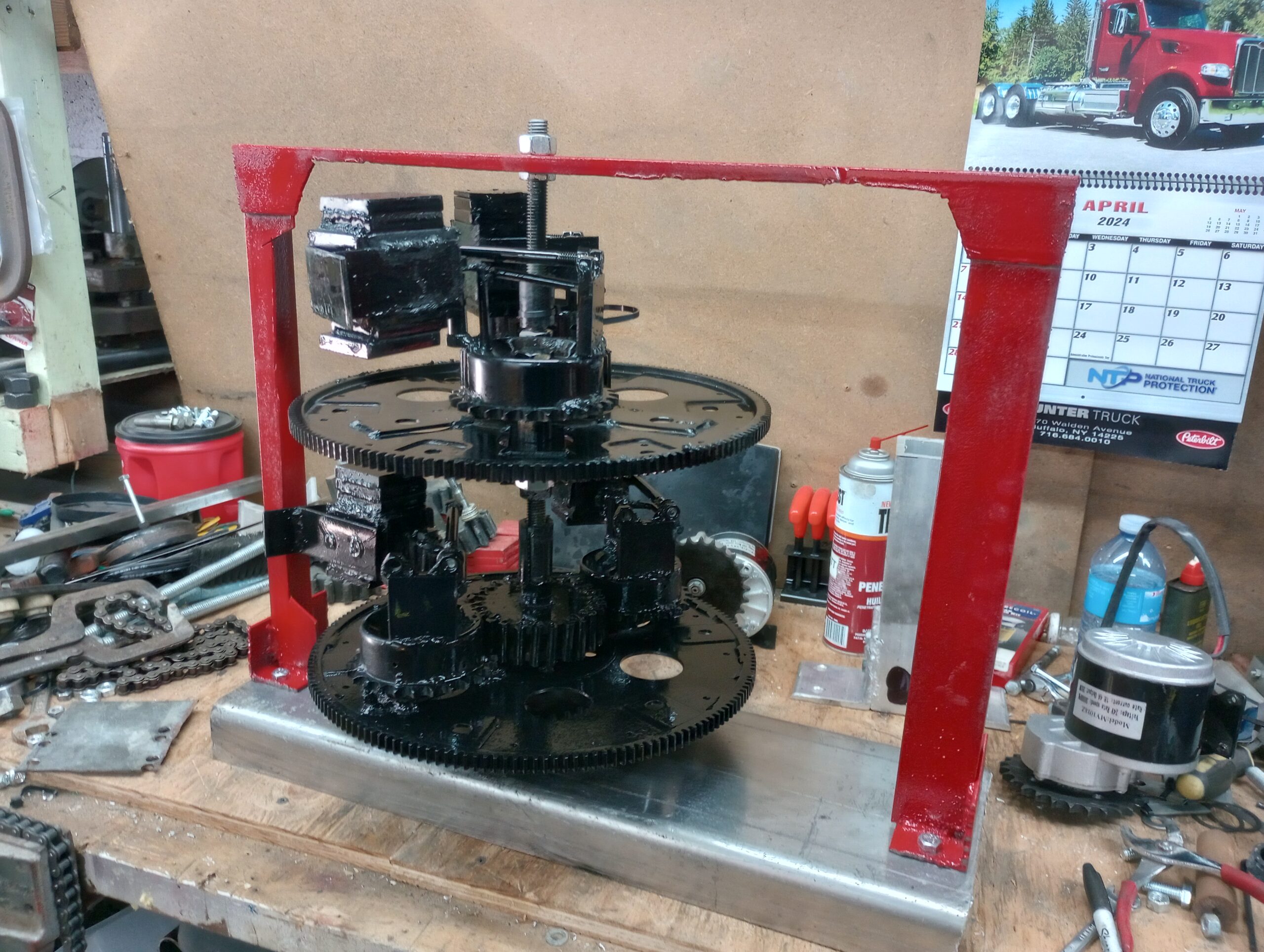
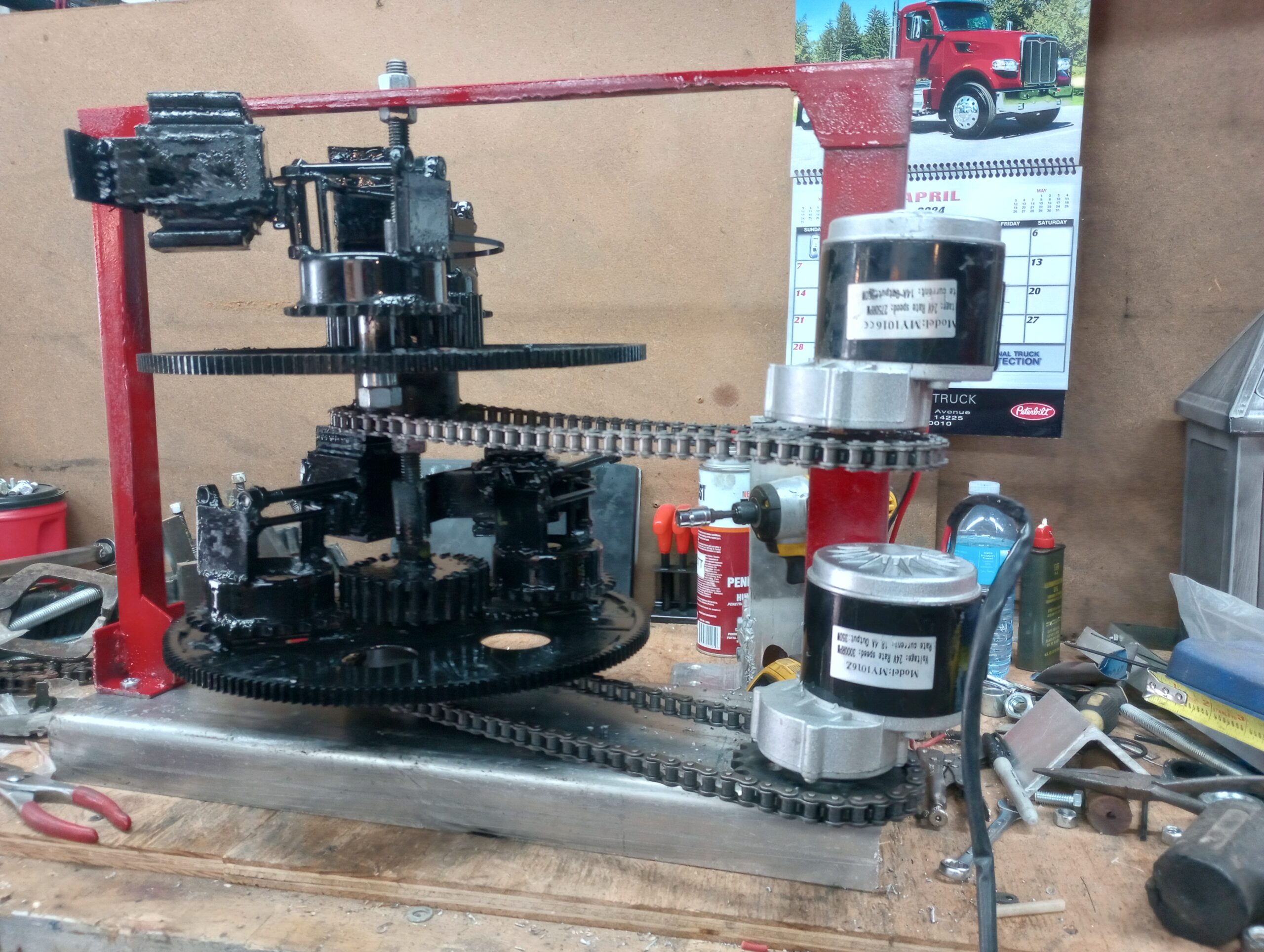
The PIE 7 is coming along very well. The first beam is done, and the second one is nearly finished too. Once it is finished it will need the QBD Coupler (Quantified Backlash Drive Coupler) installed, which should not be difficult as all of the parts made were designed anticipating it.
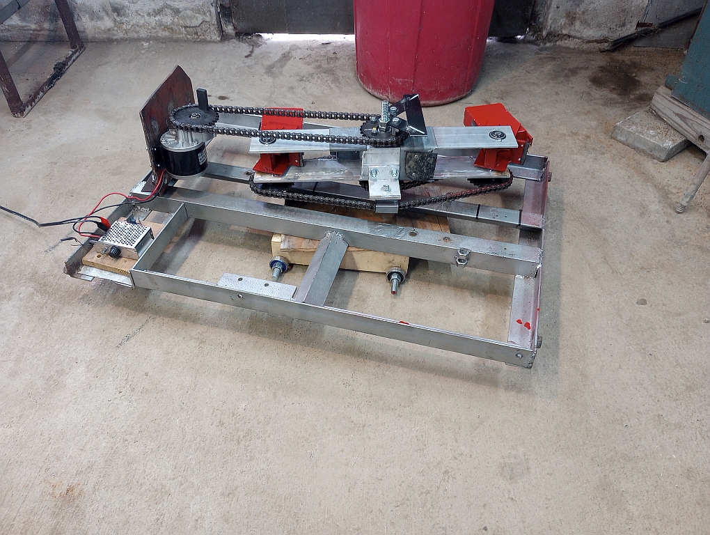
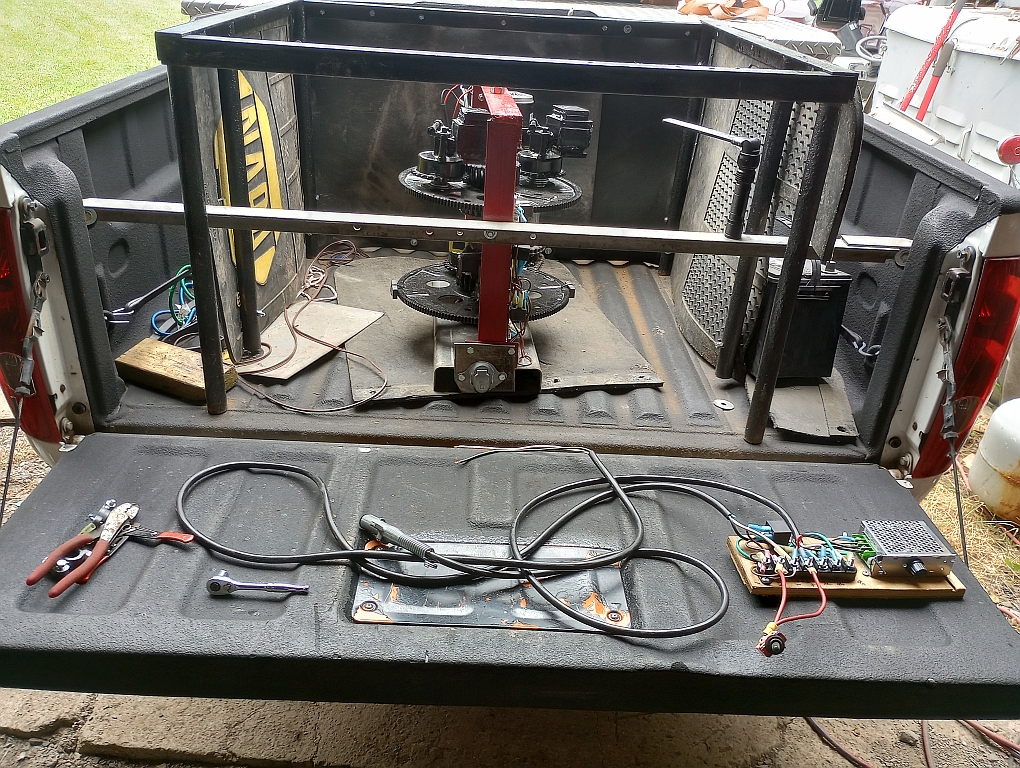
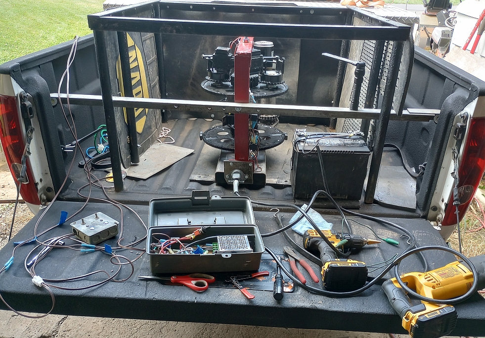
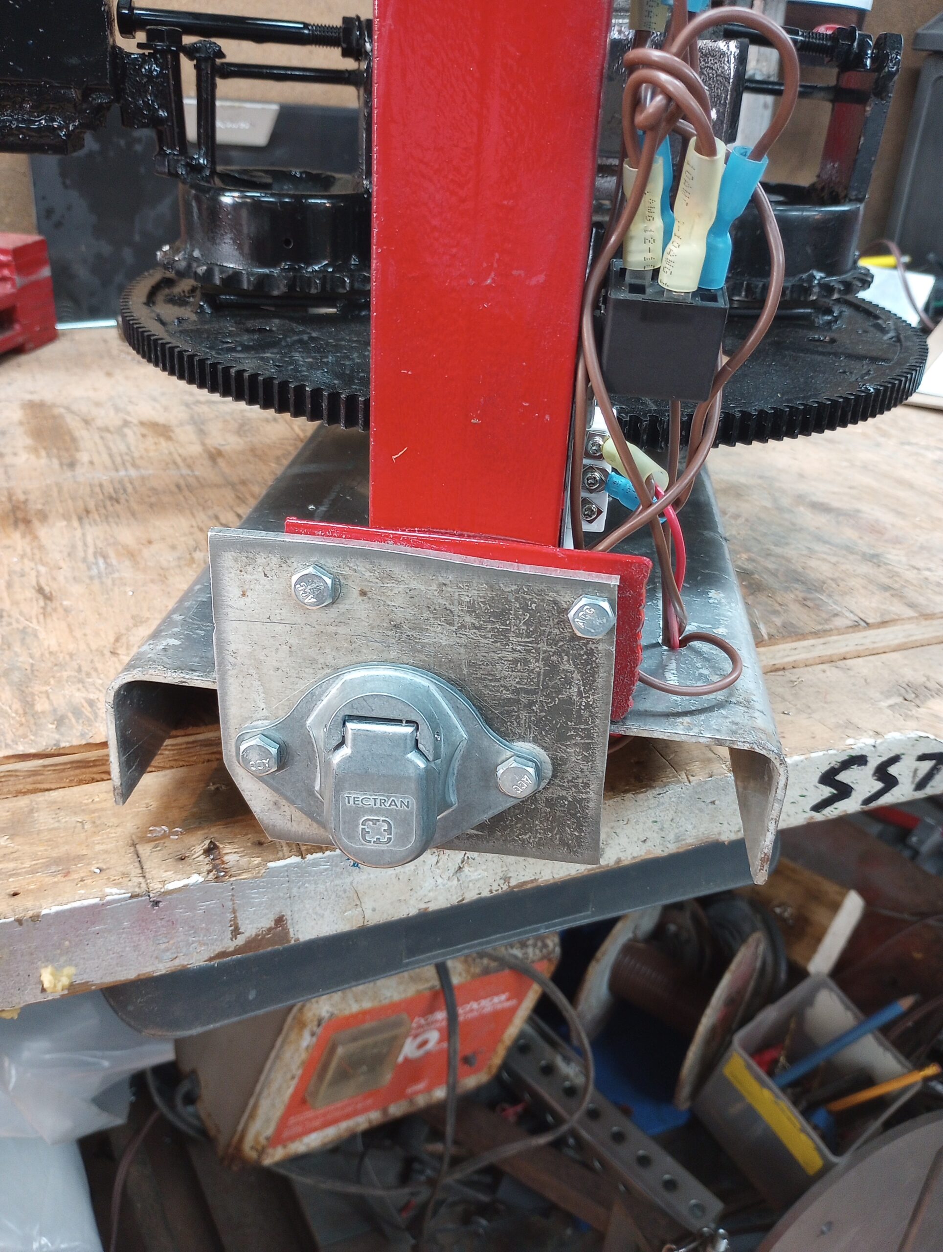
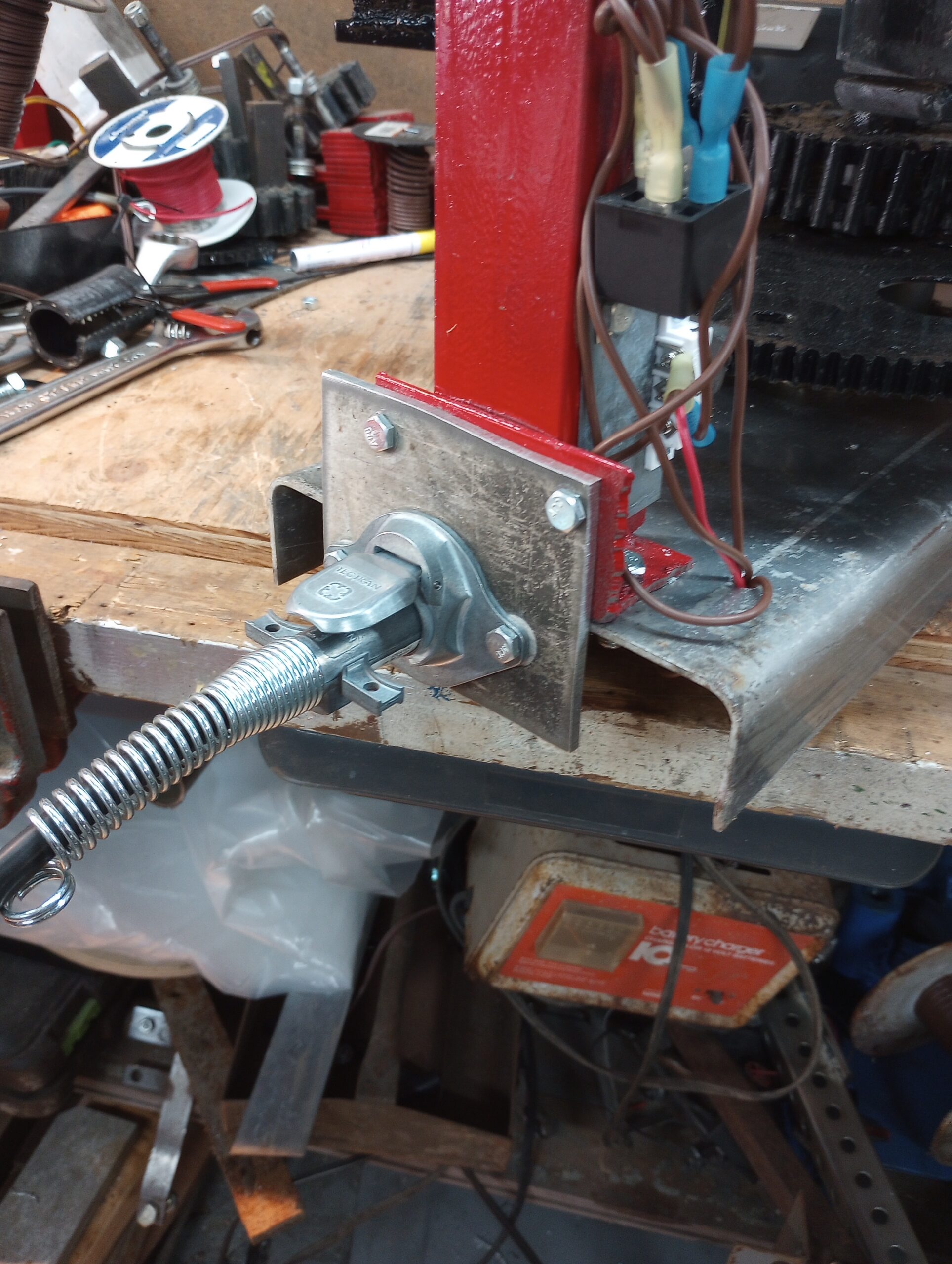
Beam 1 is set up and installed on the heavy test frame which might be the frame it stays on. Thrust is very strong even though the SDC (Speed Differential Control) hasn’t been hooked up. The last touch (mechanically) was the installation of rubber pads wherever metal to metal contact was being made. This helped to quiet it and seems to have increased the thrust a bit too.
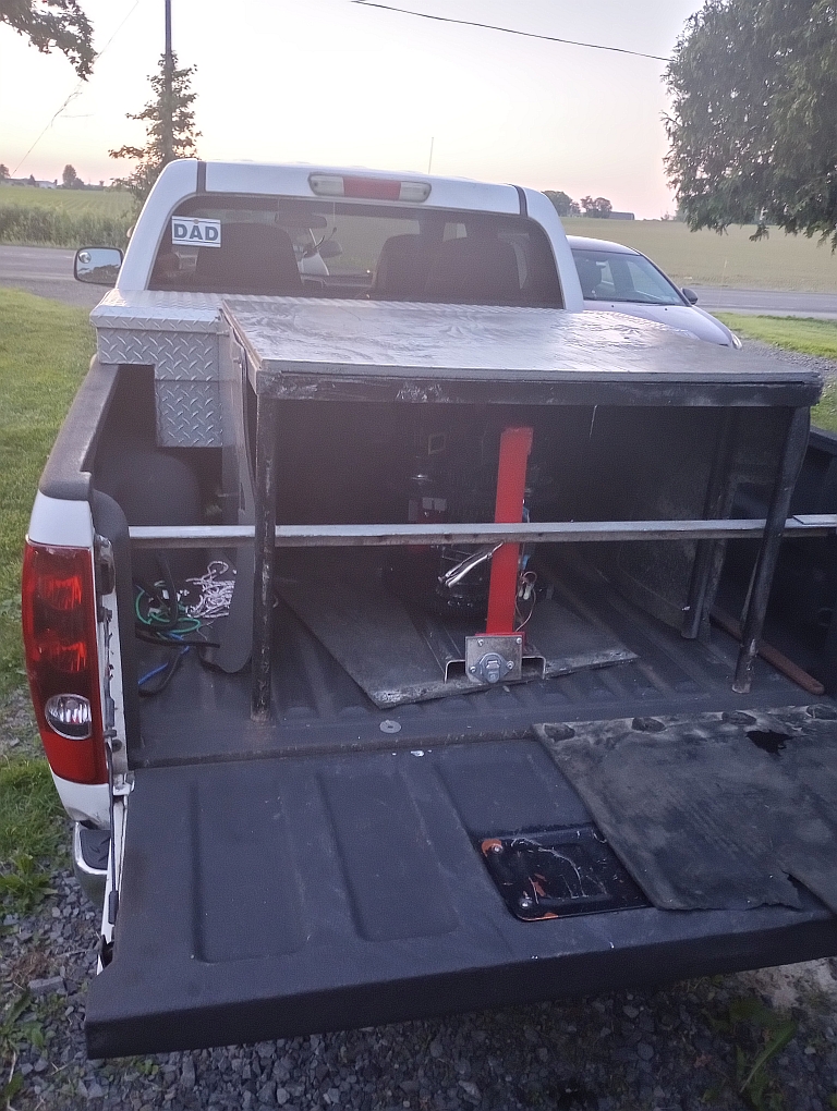
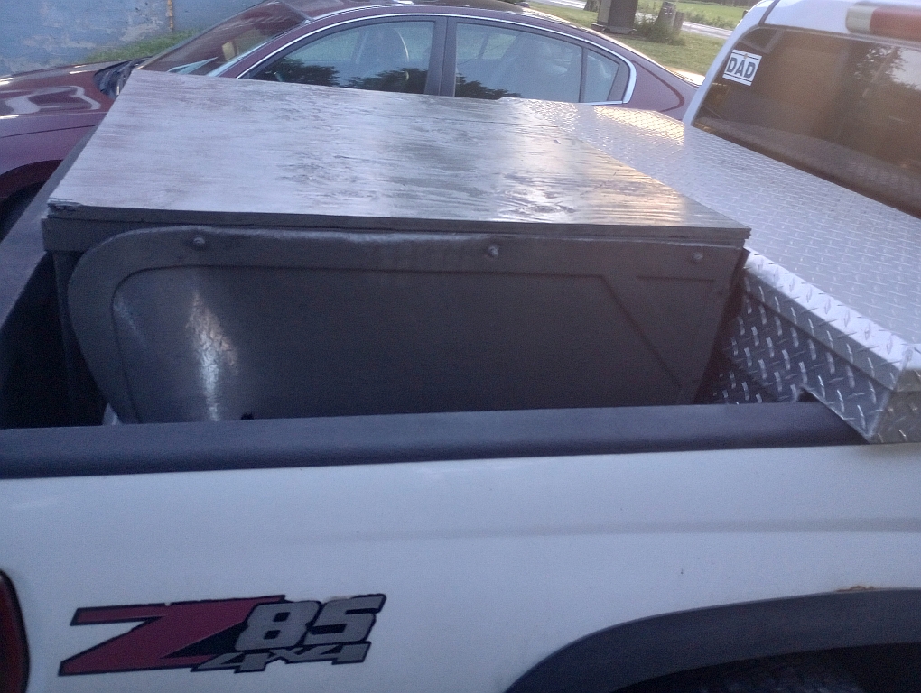
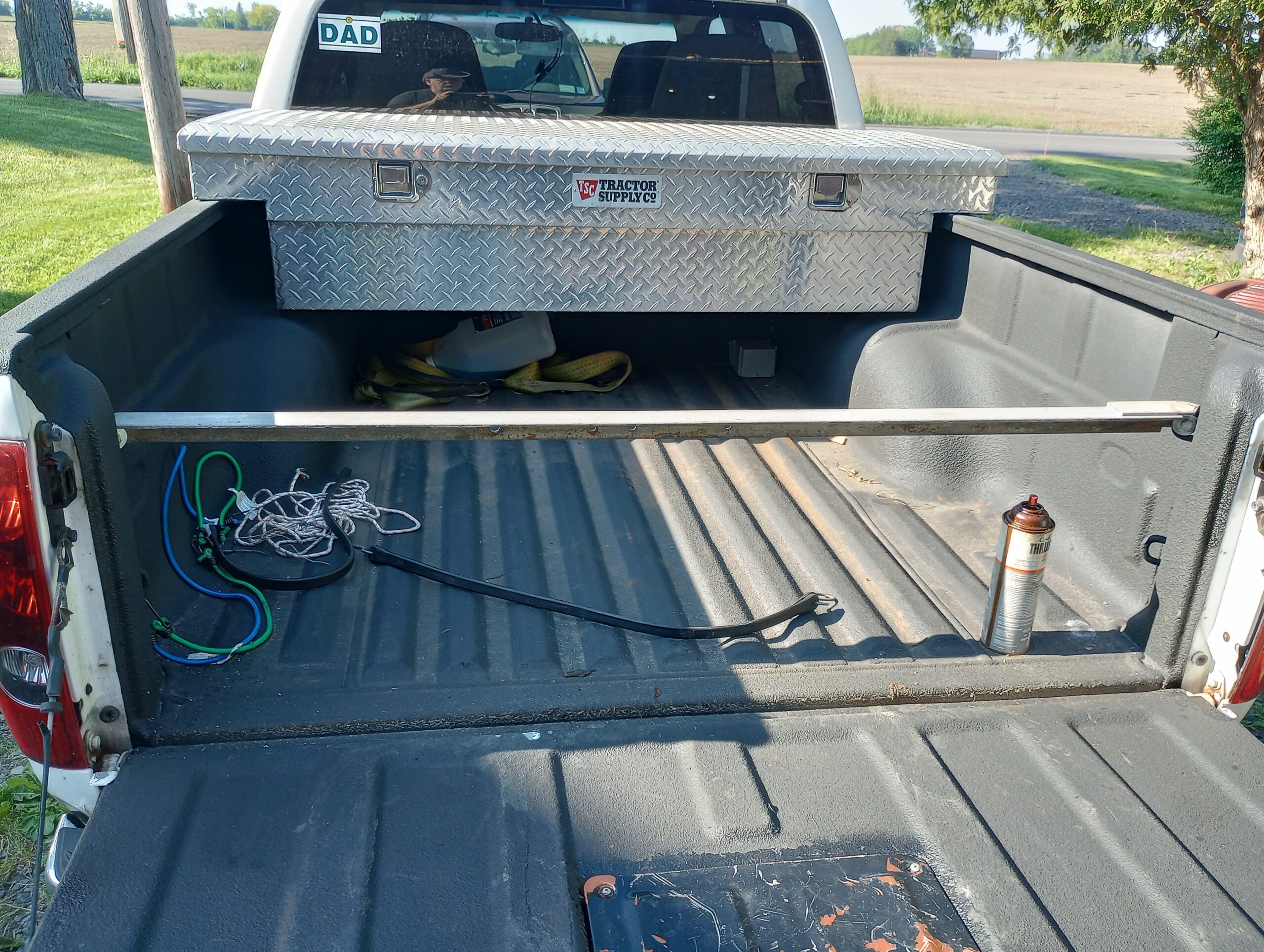
The cart I am using to move the PIE 7 around my shop has wheels that get flat spots when sitting still. With the weight of the PIE, the battery, and tools it takes just over 15 lbs. of force to start moving, and about 2 to 3 seconds before the flat spots go away. That makes the cart seem like it is sitting in a divot that is keeping it from rolling.
The videos show the PIE 7 trying to roll the cart and even shows it bending the sheet metal it is resting on as it attempts to move the cart.
Thrust has now been measured on a slanted ramp setup. Without the SDC and a very weighty and smooth rolling cart, there is too much pulsation and reversion to effectively see the PIE 7 “self-propel”.
The latest modification to the beam(s) is the addition of rubber pads which are attached to any metal-on-metal contact points. They serve to protect the metal parts, reduce noise levels, and increase the duration of each pulse which effectively strengthens thrust output.
I am planning on doing more APEC style presentations soon. I really hope all of these efforts build interest and maybe people will want to start replicating the PIE prototypes with variations of their own.