As PIE 6.0 road testing winds down (more on than soon), and we are planning for the next phase, I noticed an issue while speaking to a trusted associate. I would say PIE and he would ask if that’s the aluminum one, or I’d say Trammel engine and he would think I am speaking of the PIE 6.0 that we have been testing. I thought to myself that there must have been a similar confusion in pre-war Germany at the young Volkswagen company. As they basically had 2 models, with a small number of options, people would confuse the “Beetle” with the “Bus” (Americanized names) so they simply labeled the Beetle as a “Type-1” and the then unnamed little van as a “Type-2”. If it worked to help reduce confusion at VW, it should also be able to help here at Stclairtech R&D!
For the sake of simplicity:
- PIE – If it is a planetary gear design with a stationary sun gear the PIE may easily be referred to as a Stclairtech Type-1, which can be shortened to ST-1 in documentation.
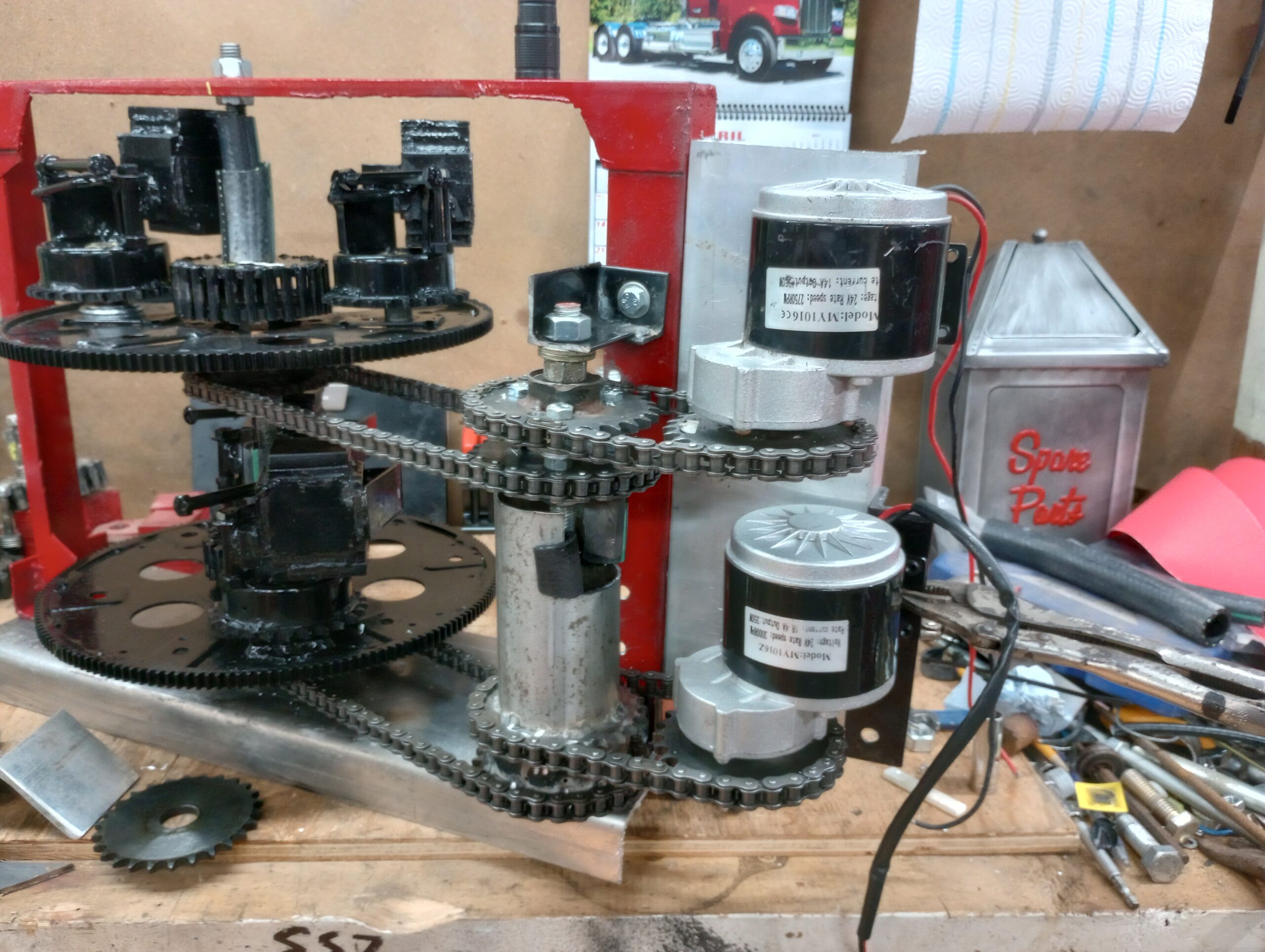
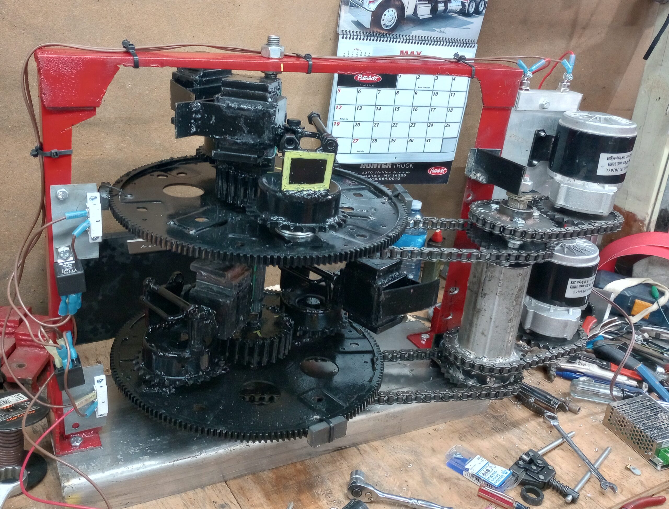
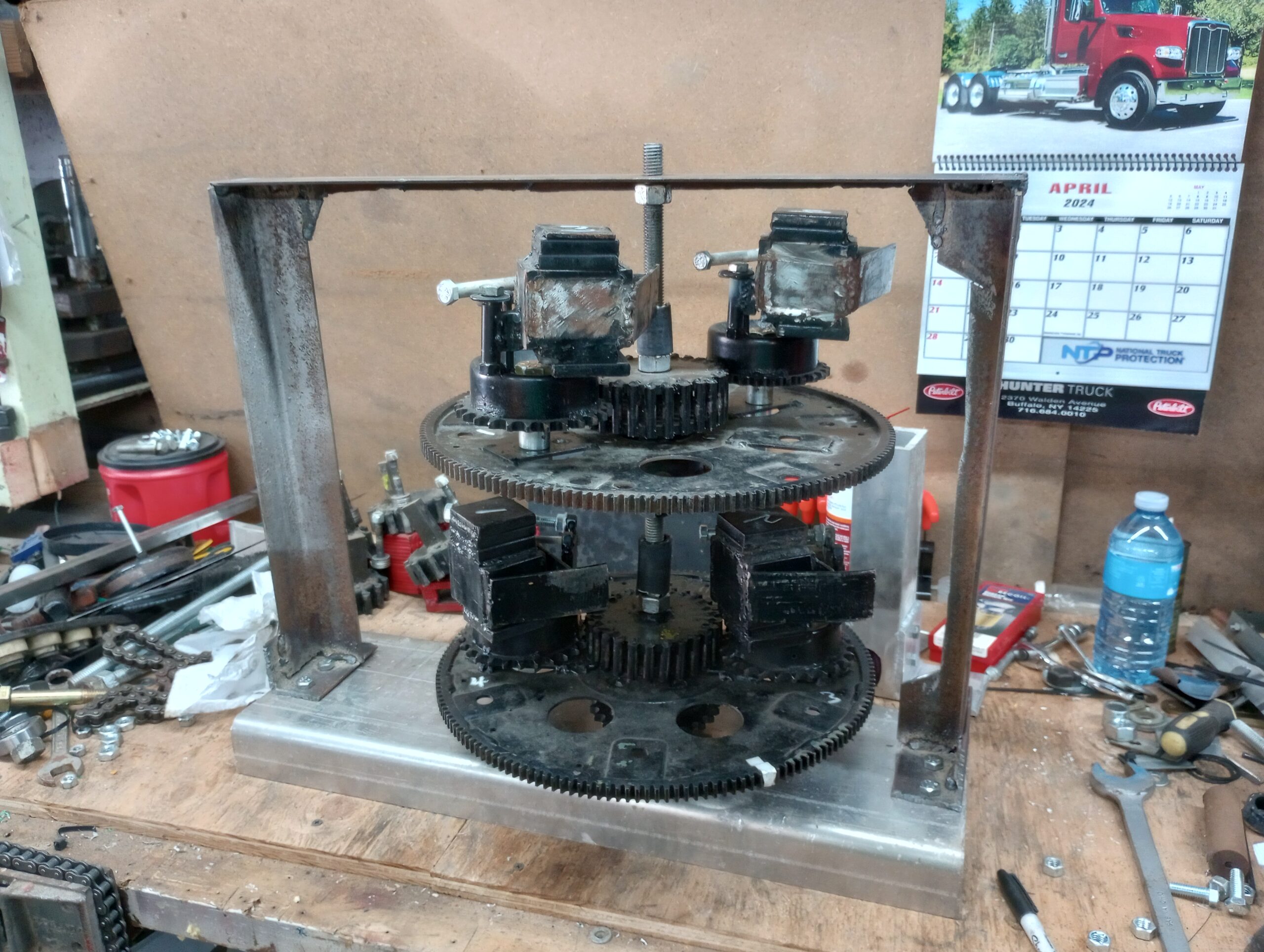
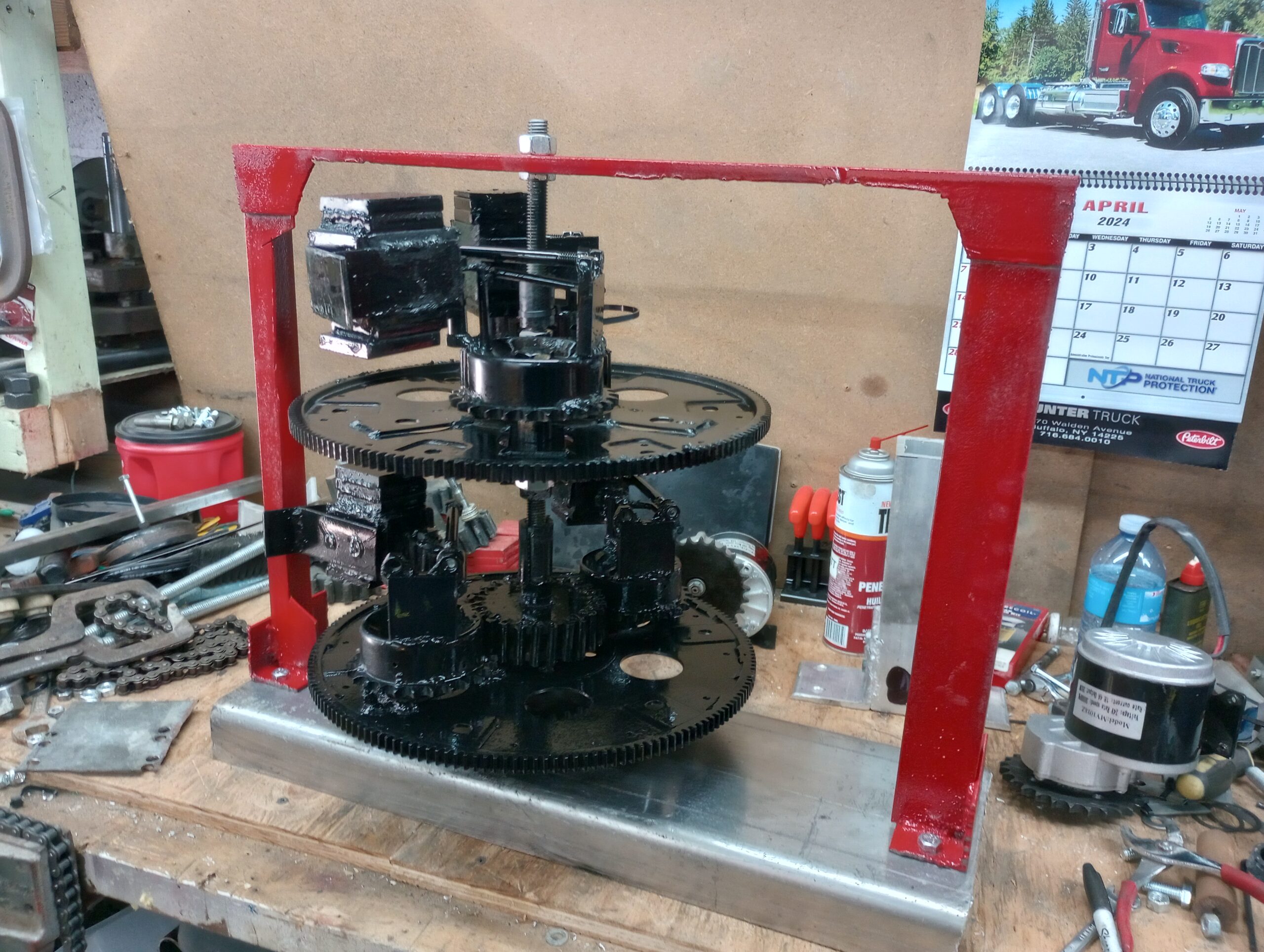
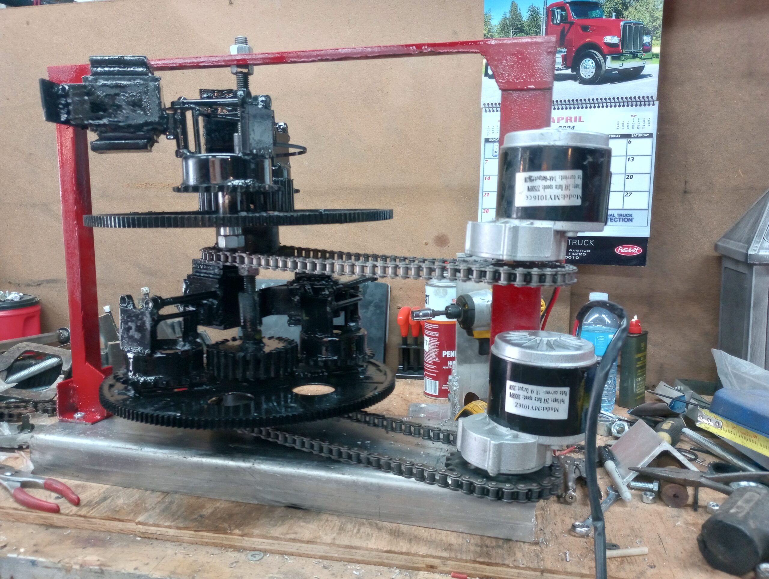
- Trammel – If it uses rotating discs with an X cut into the middle of it, the Trammel engine can easily be referred to as a Stclairtech Type-2, which will be shortened to ST-2 in documentation.
We will also be creating simplified identifier logos for the Stclairtech Type-1 & Type-2 (ST-1 & ST-2) soon. Until then: Stclairtech Type-1 (ST-1) is a PIE. Stclairtech Type-2 (ST-2) is a Trammel.
To anyone confused by the terminology issues, I understand the confusion and I want to keep it as simple as possible. The old axiom identified as KISS (Keep It Simple Stupid) still stands in our workshops, although we do tend to reverse the simple and stupid for a clarified statement making it Keep It Stupidly Simple. In that spirit, here is a short glossary of words, terms, and abbreviations referring to specific components of the thrust-generating devices we are developing here at Stclairtech R&D.
Abbreviations unique to our mechanical closed-loop propulsion system(s):
- PIE = Pulsed Inertial Engine
- ST-1 = Type-1 = Stclairtech Type-1 = PIE
- ST-2 = Type-2 = Stclairtech Type-2 ST-2 = Trammel engine
- SDC = Speed Differential Control
- QBD = Quantified Backlash Drive
- QBC = Quantified Backlash Coupler
- AMP = Active Mass Point
- FP = Force Point
- CLIP = Closed Loop Inertial Propulsion
Definitions & terminology unique to our mechanical closed-loop propulsion system(s):
- Closed Loop Inertial Propulsion = Propulsion produced without propellant.
- Pulsed Inertial Engine = Type-1 Closed Loop Thrust Producing Engine.
- Trammel engine = Type-2 Closed Loop Thrust Producing Engine.
- Mass = Any mass or weight, generally referring to a mass used to produce work.
- Active Mass = Mass that isn’t “fixed” in place and used to produce work.
- Active Mass Point = The point where an AMP applies force to do work.
- Force Point = The point where force is transmitted to the assembly.
- Speed Differential Control = Device used to change rotational speeds dynamically.
- Quantified Backlash Device (Drive or Coupler) = Coupling device with a specific calculated (quantified) amount of backlash, connected between rotating assemblies.
- Thornson Drive (EZKL) = A type-1 device which paved the way for modern Pulsed Inertial Engine technology.
- Reversion = The act of an object reversing its direction of movement or thrust.
- Wheel or Disc = The base rotating assembly currently being used to rotate the masses.