It has been MONTHS since I updated here… A lot has happened in my life and in the shop! For those interested, I have switched gears in my professional life. Since the change is quite dramatic, I have been under some stress “getting in the groove”, but it is a needed change and I’m getting it all figured out.
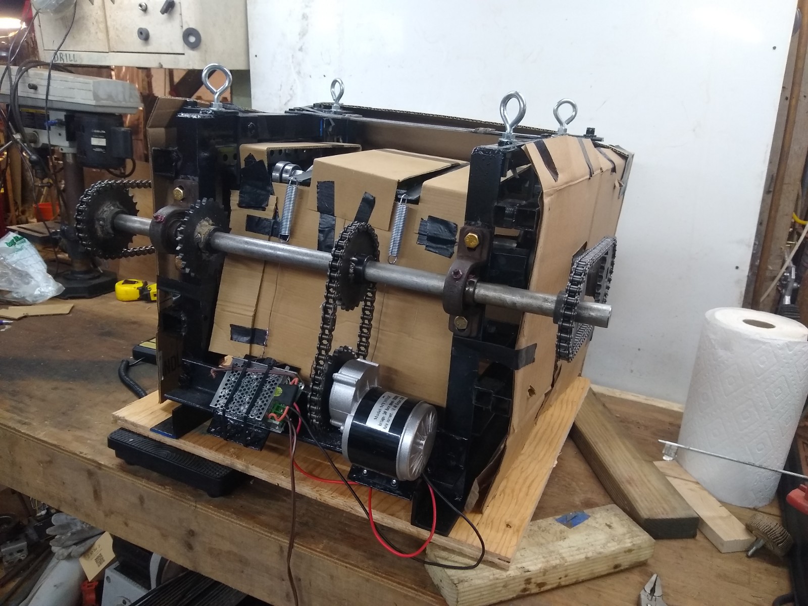
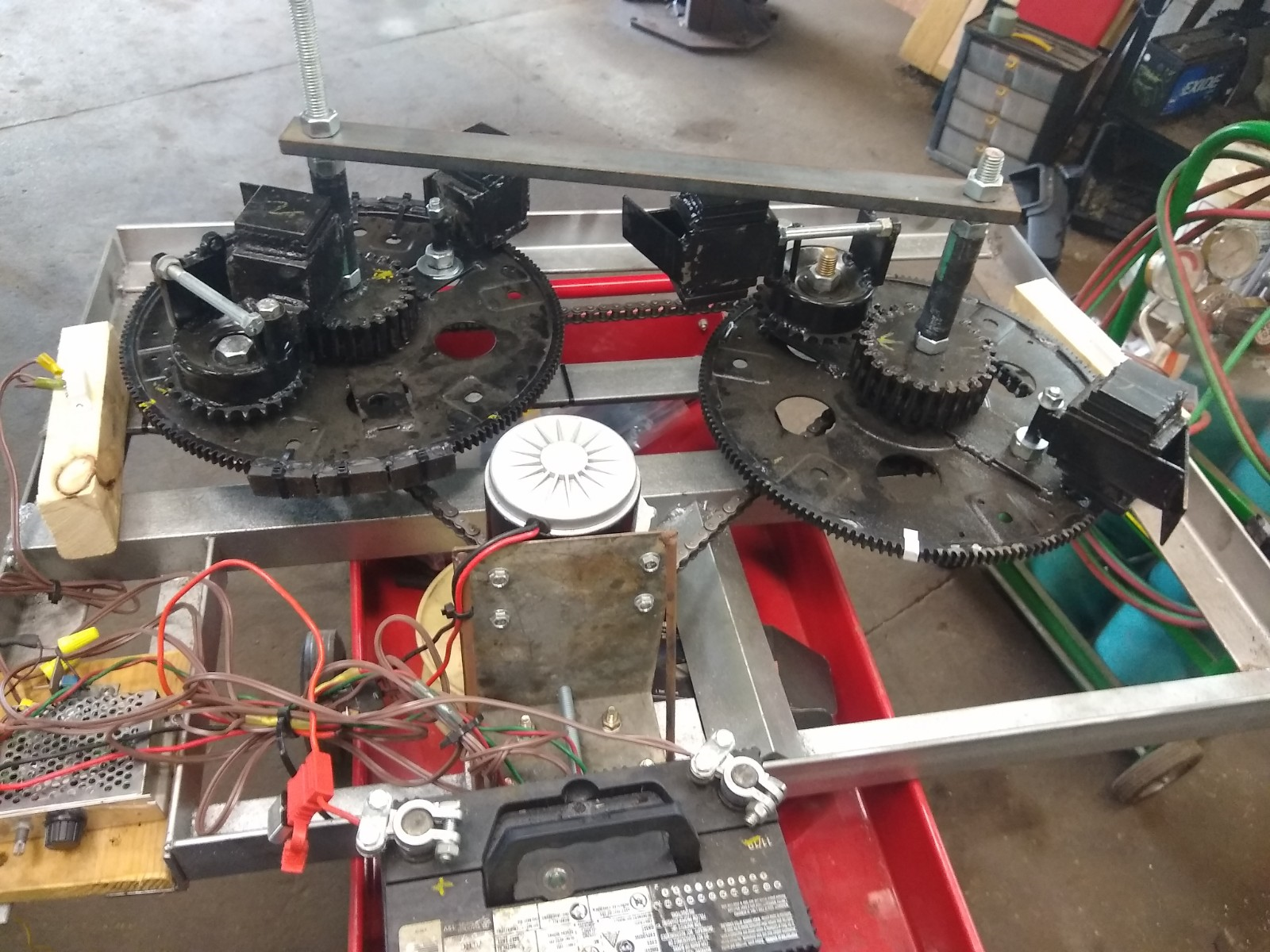
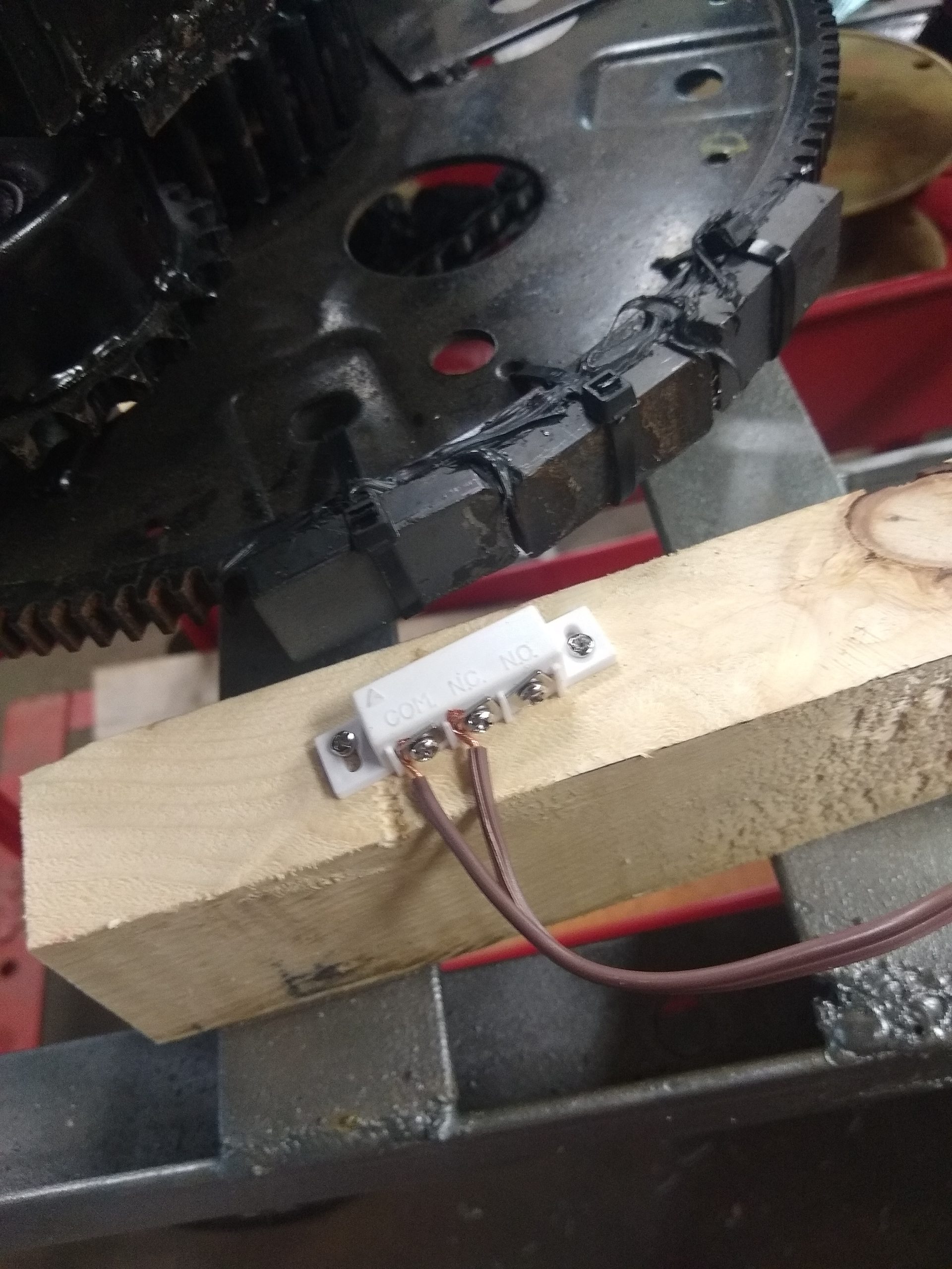
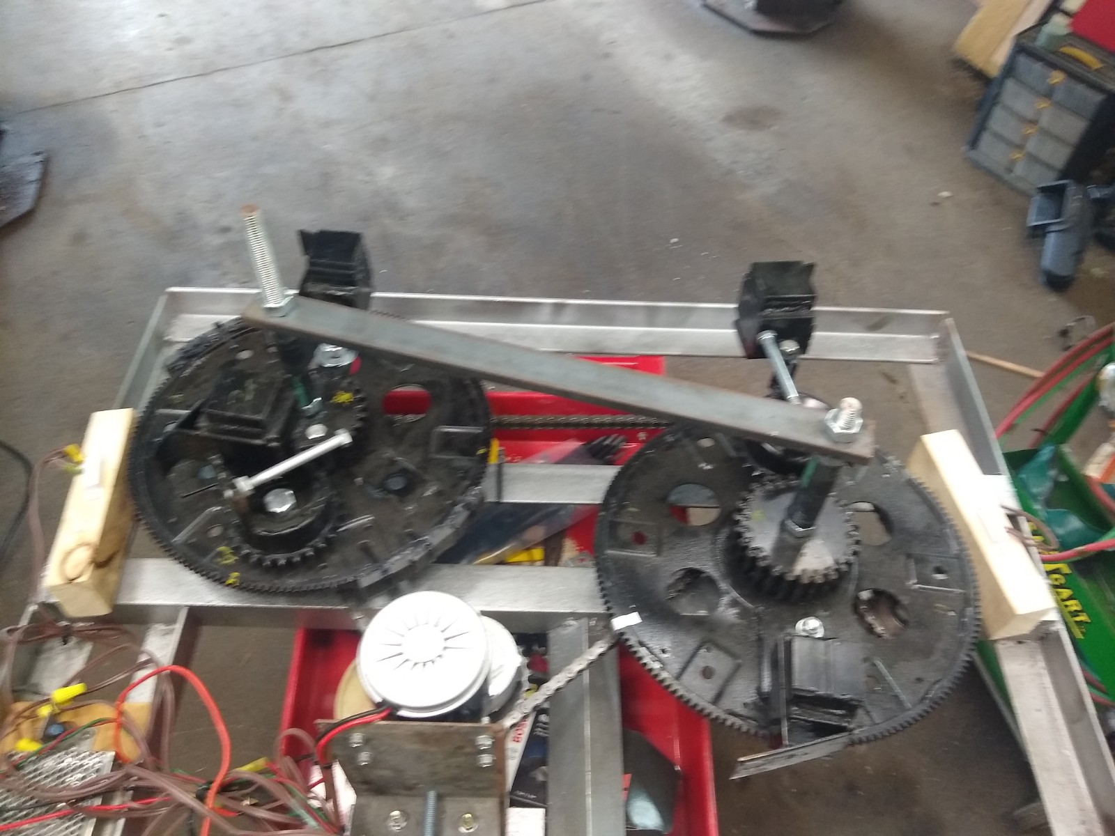
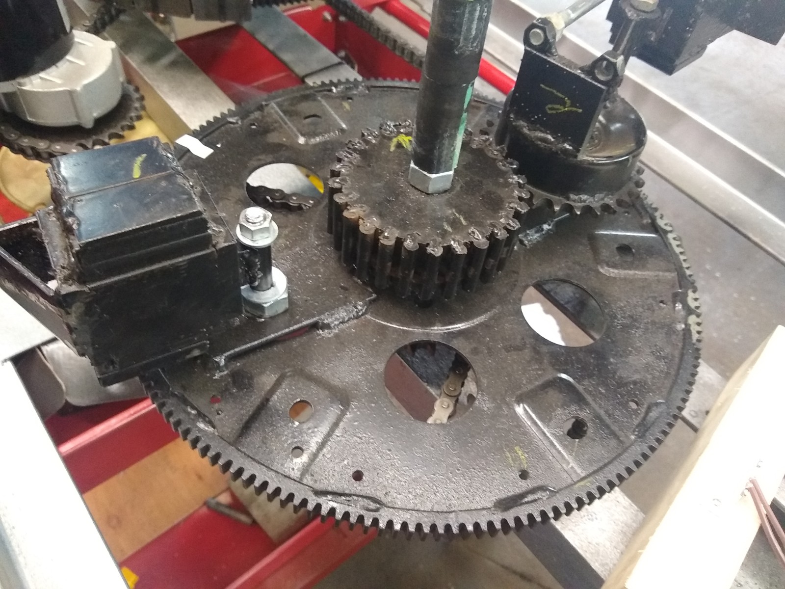
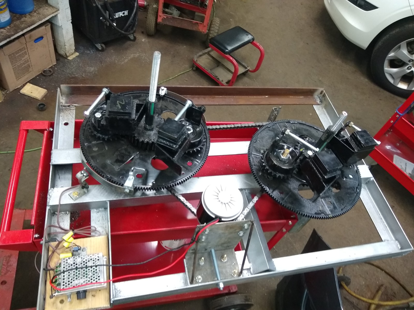
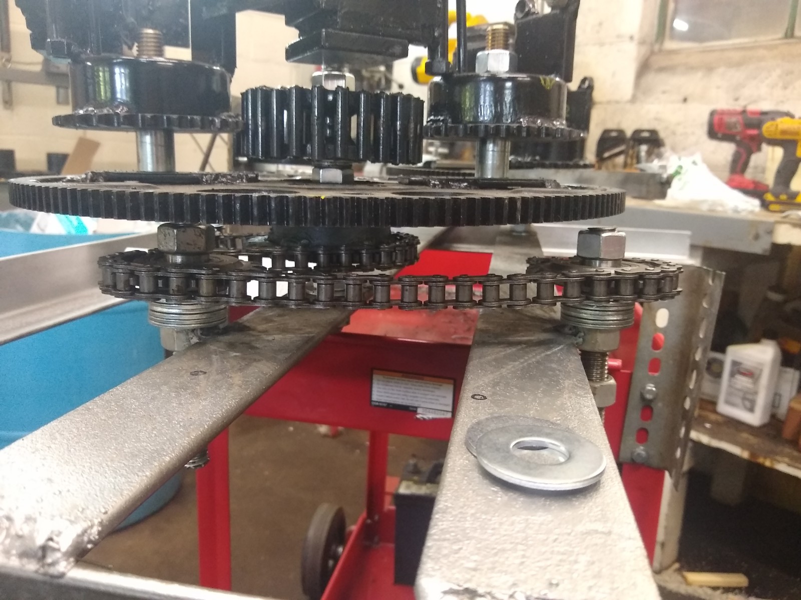
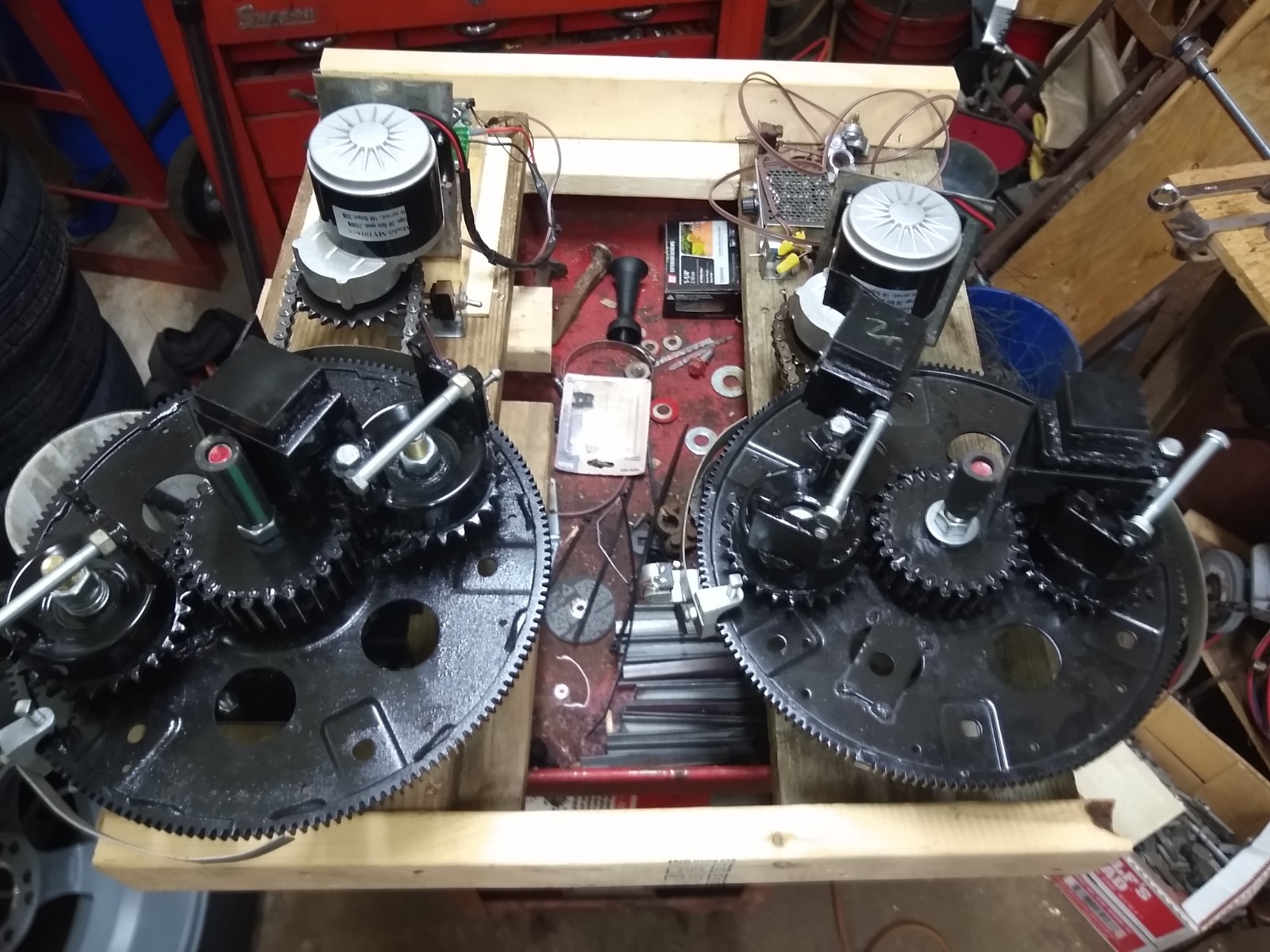
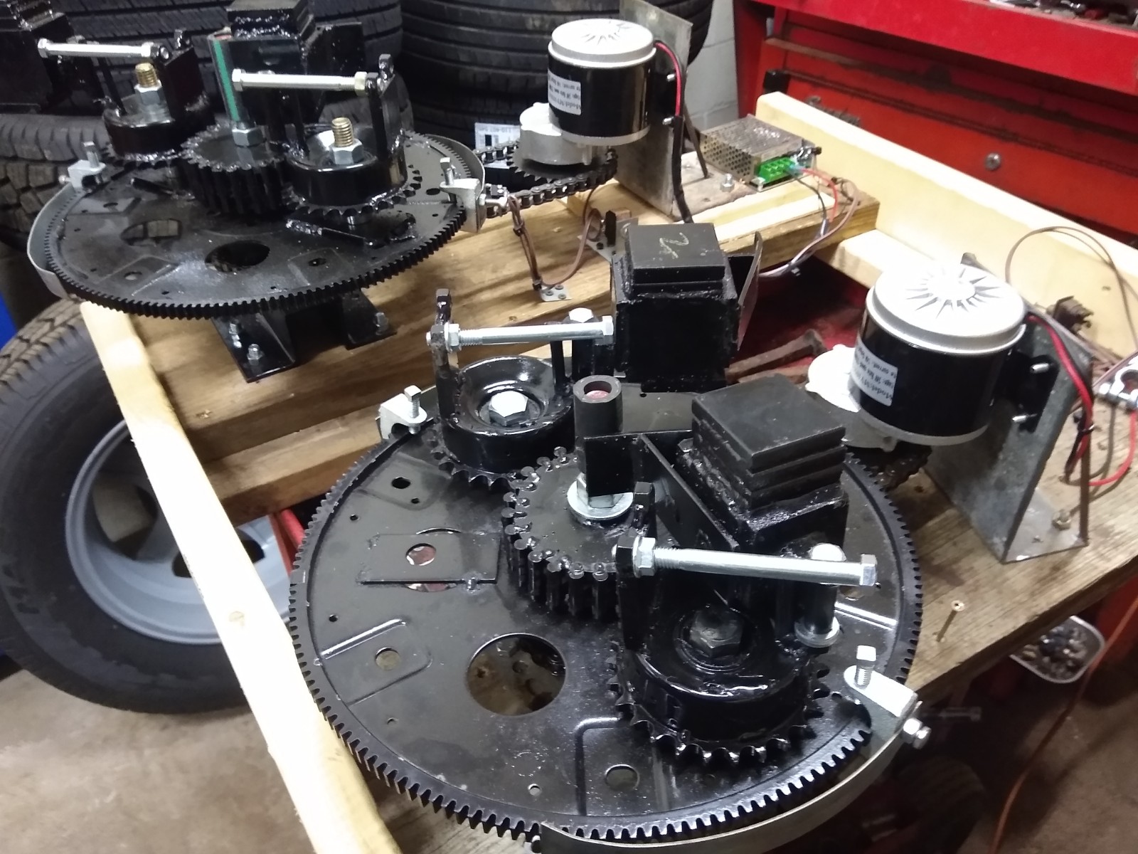
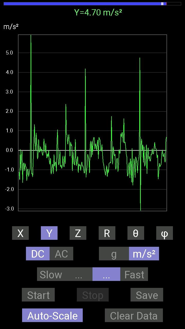
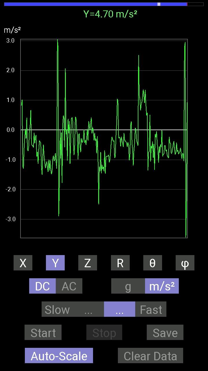
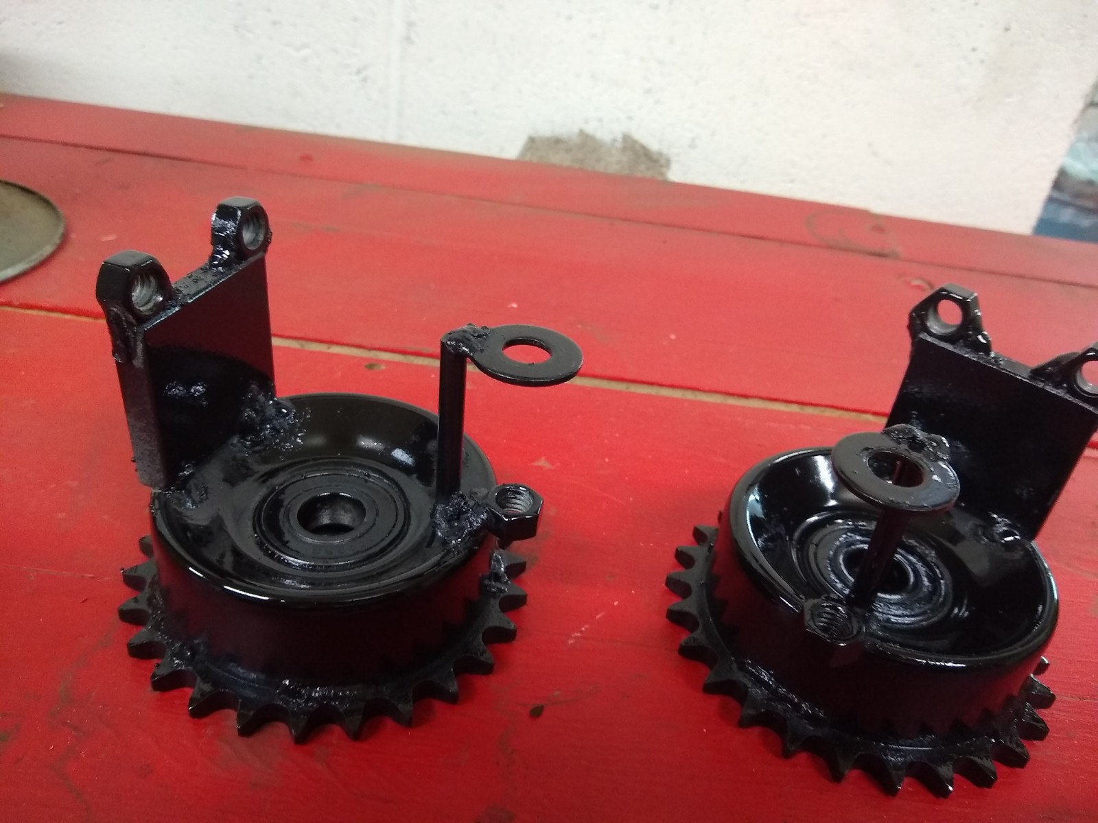
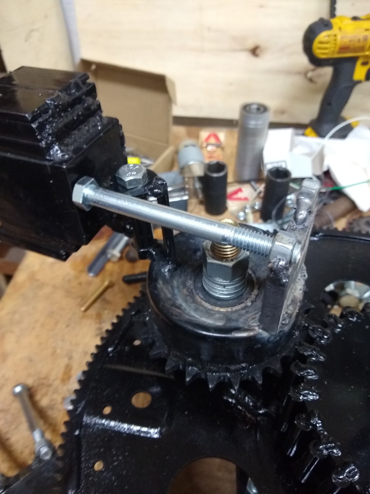
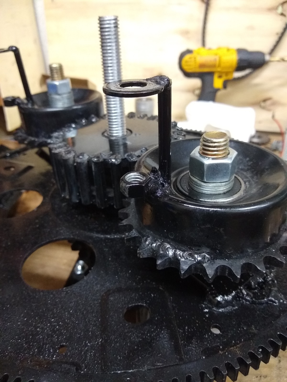
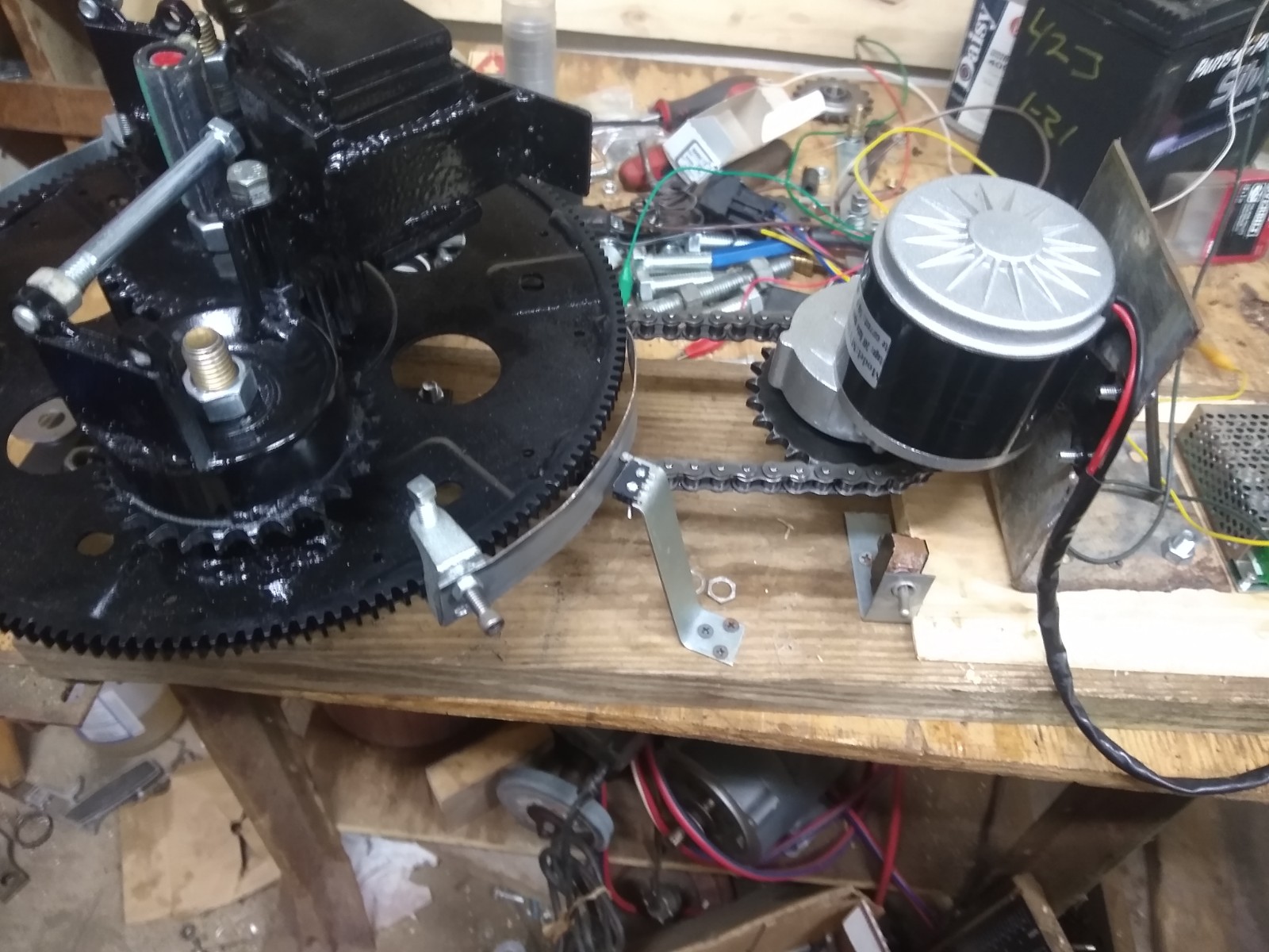
The PIE X aka Trammel Engine is coming along. Inside it (still not ready to reveal too many details) are some components which were made too weak, but they have been rebuilt and replaced with much more robust pieces! I have experienced some intermittent thrust and have kept moving forward with this as much as possible. I also recently received a much-improved motor and speed controller which is now installed.
It has become quite evident that as I contact potential business partners and investors, I need a small and lightweight demonstration model which can be taken along to those meetings. With that in mind, I introduce the “PIE Mini”. The PIE Mini is a nearly complete, single weight, working, demo model which is really small and light with plastic gears and a hollow tube instead of a large “wheel”. It’s power source is a super cheap cordless screwdriver from Harbor Freight. Although it is intended to be a portable demonstration device.
I believe it will also be a design which could become the first model of a sellable working model for science minded people everywhere to experiment with.
There are a couple of videos of the PIE Mini on BitChute .
I have also now run a live demo of the Mini at the APEC conference on Feb. 27, 2022. During this presentation I showed that the unit actually needs mass to operate and that is really it’s only environmental prerequisite. I should be posting that presentation on my BitChute and YouTube channels very soon. Until then, here is a link to it on the American Antigravity YouTube channel.
I want to thank Ross Small for joining the video conference with a presentation of his own. He is building a “linear thrust” machine in the hopes that it will be a helpful learning aid for everyone to better understand the mechanism of inertial propulsion. Some of those very principals are integral to the Trammel Engine, and have also got me thinking about other, future, design builds.