11/9/2022
It has been a long summer of trying to balance my time in my workshop/lab and my career as a Parts Associate, now promoted to Supervisor. Sometimes I think that I must be doing a good job, but there are some difficult days when I think that I am the supervisor because nobody else wants the headaches…
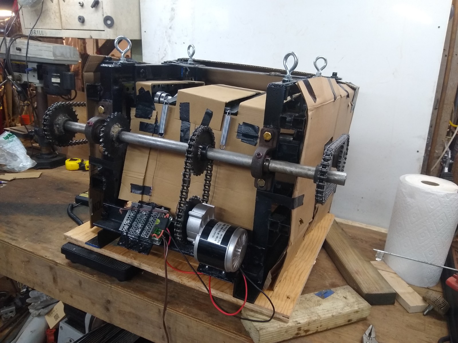
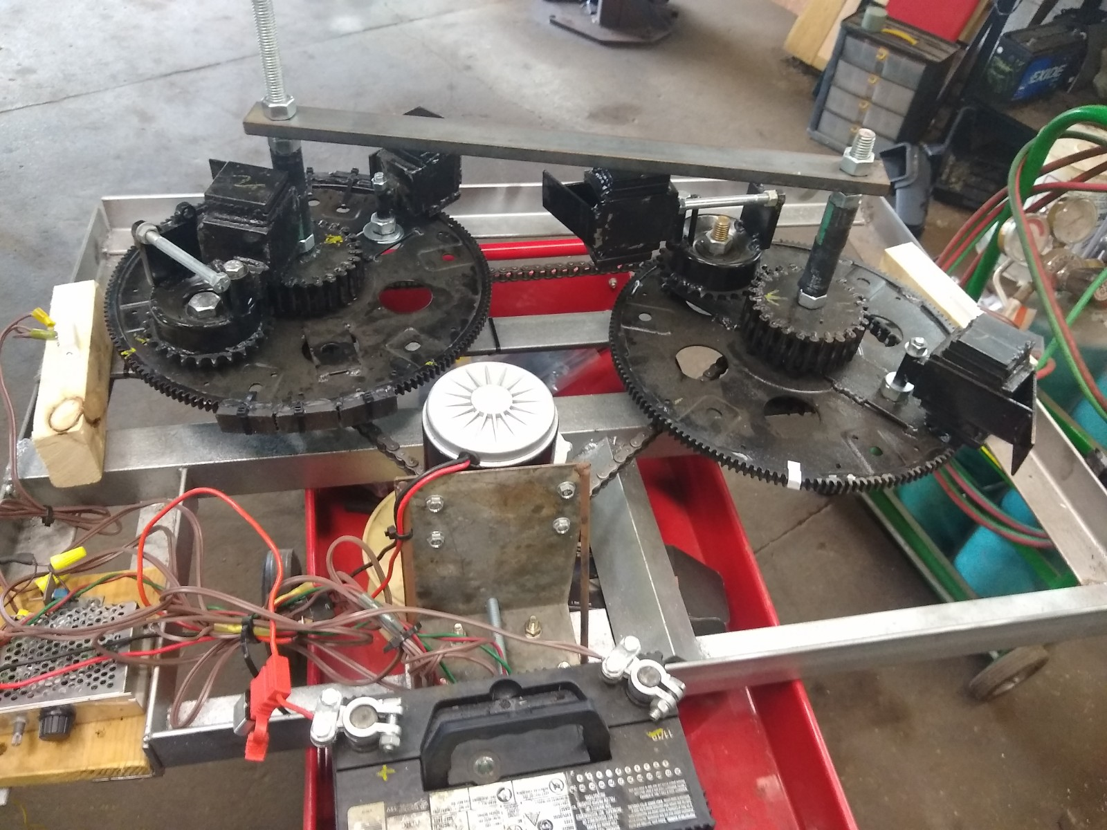
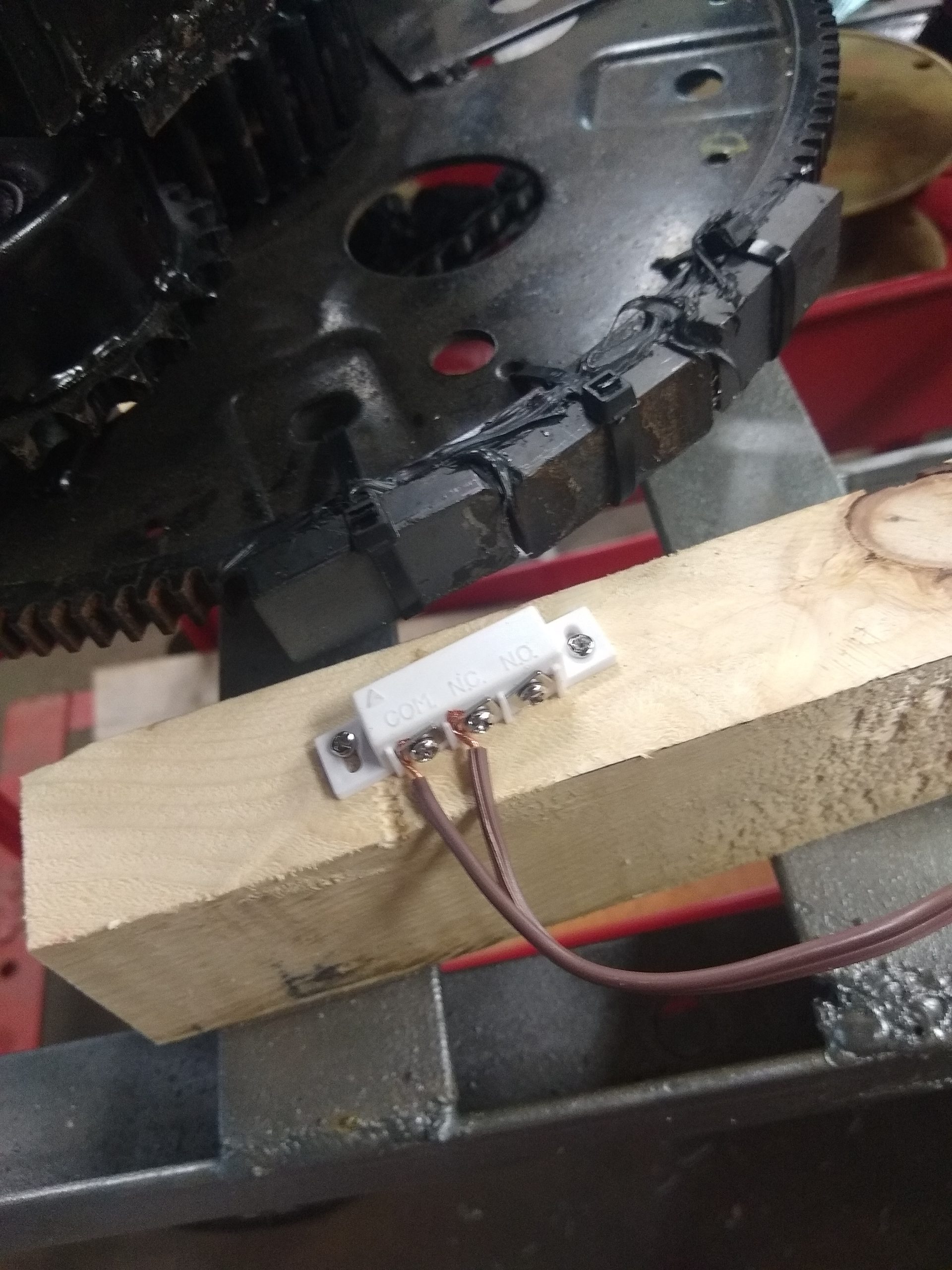
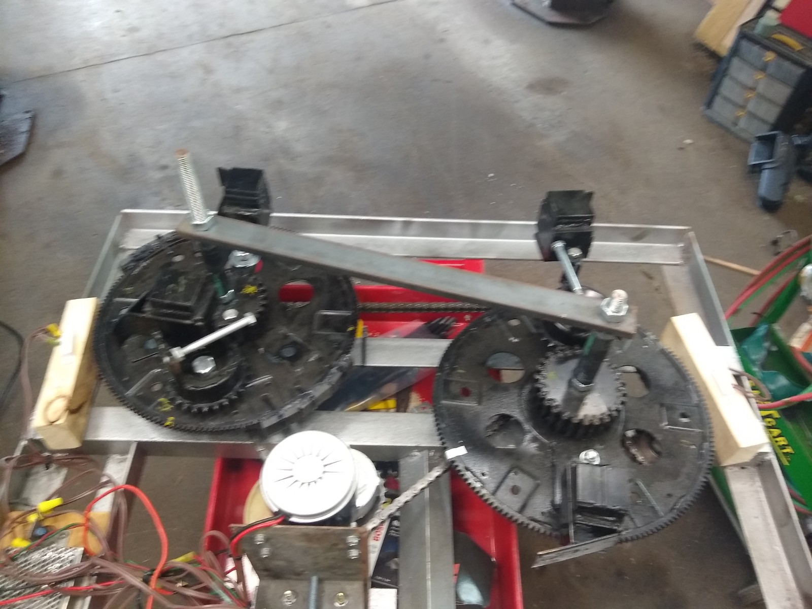
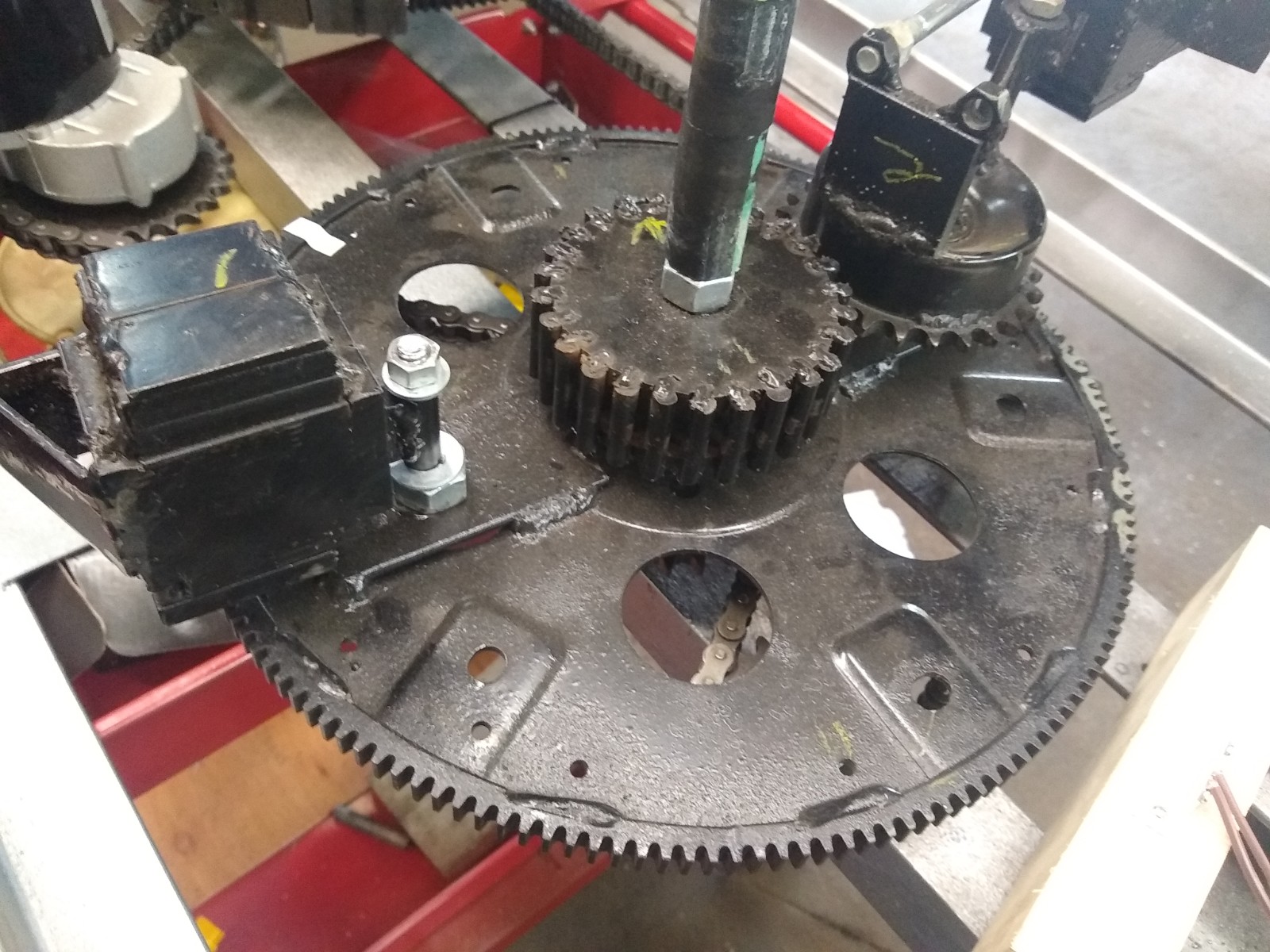
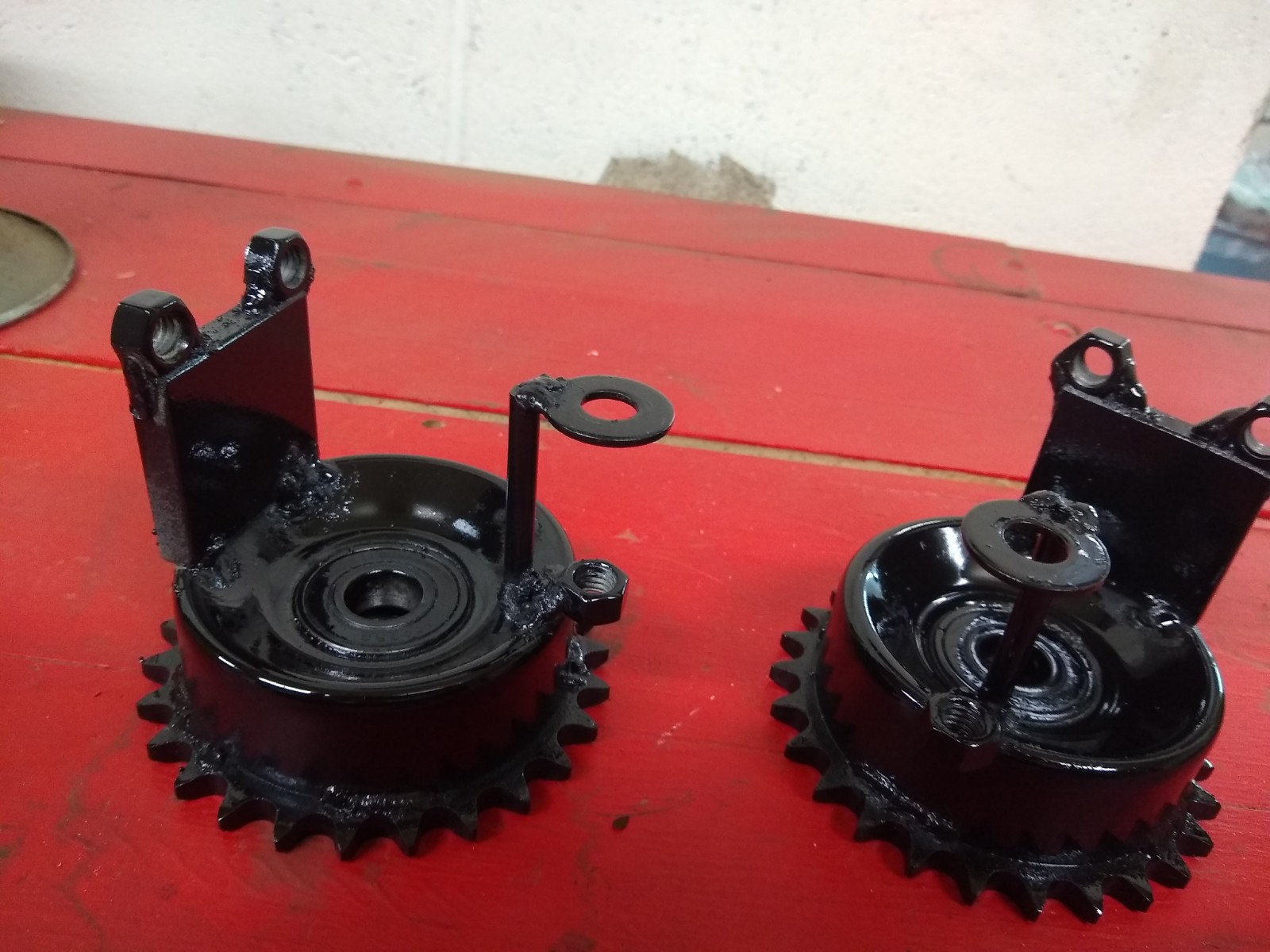
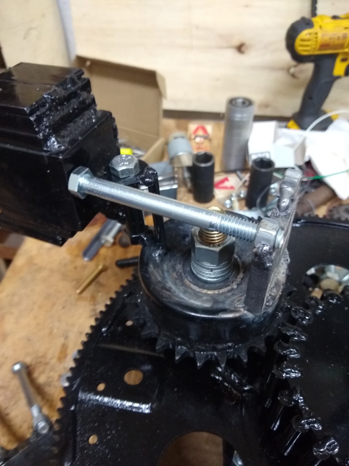
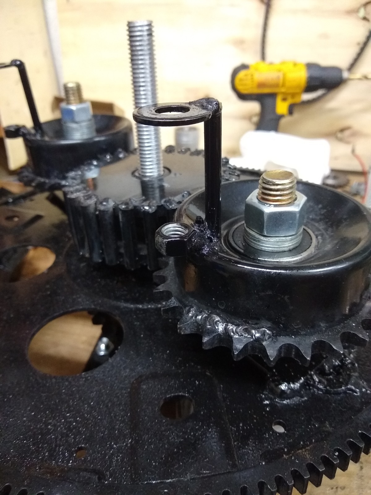
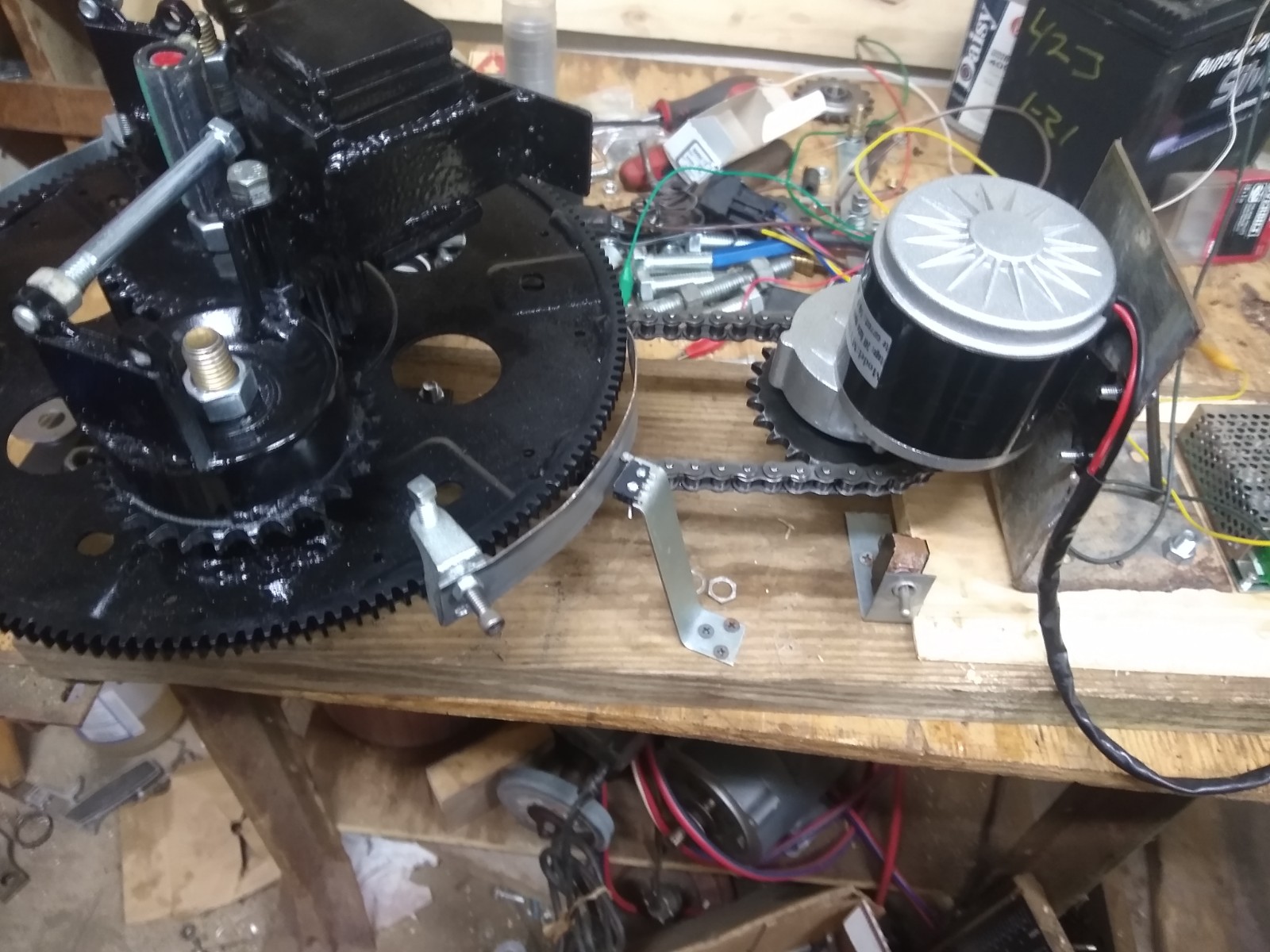
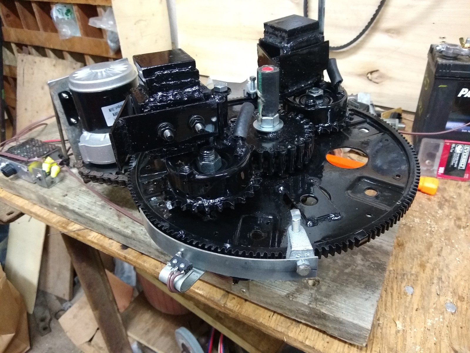
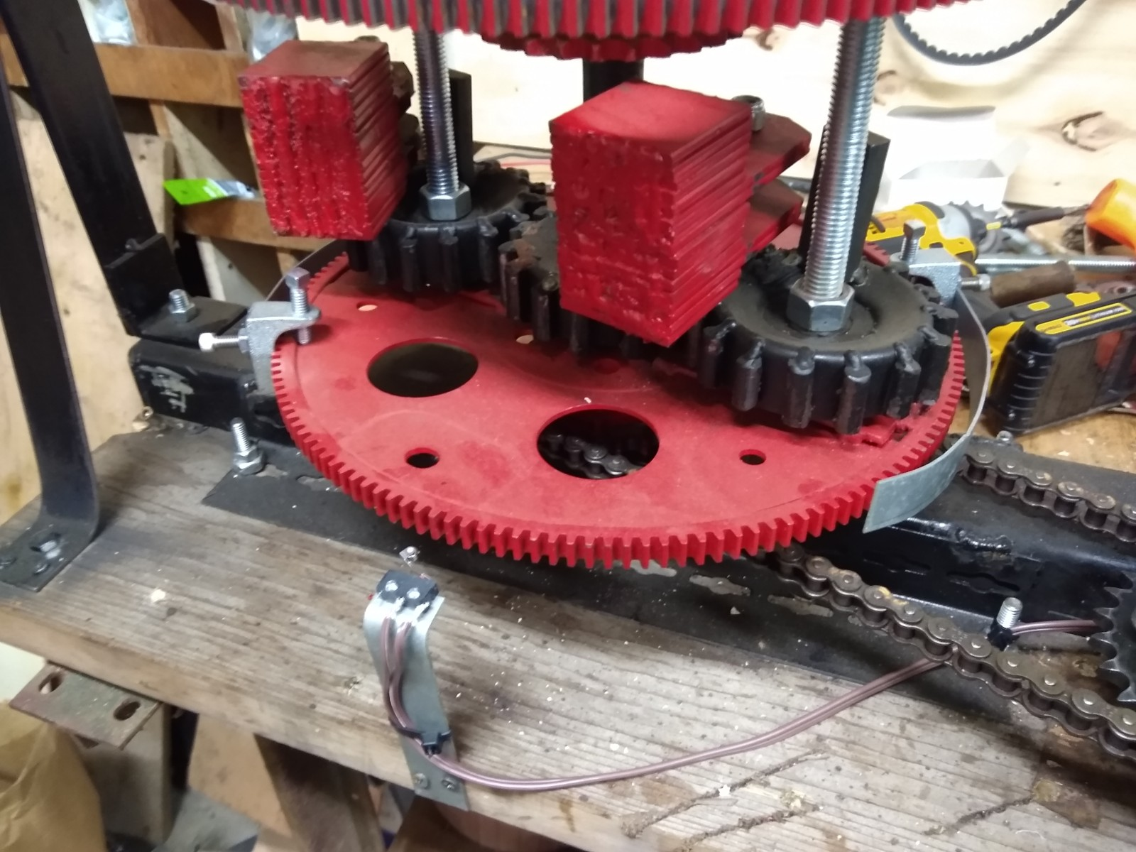
Trammel Update: The Trammel Engine has been rebuilt over and over and now 99% of the internal motion is now working as expected. There are internal components I call con-rods (connecting rods) which only pull and never push, then there are push-rods which can only push and cannot pull. The con-rods are now of a very strong design and their length is adjustable. We had multiple con-rod failures until this design was implemented.
The problem appears to be with the push rods. It was originally thought that their purpose was more of “timing” between the lower halves of the motor, so they would only need to basically “take up slack” with a spring load. This now appears to be incorrect. It seems that they must actually provide a “hard stop” which only pushes but cannot pull. Springs will still be used, but more as an ant- rattling device (I think).
The constant trial runs and failures precipitating rebuilds and repairs have really taken their toll on me mentally… I need a freakin’ win for crying out loud! So I am now (on an opposite workbench) building a PIE 5.0! It is a culmination of PIE and Trammel knowledge gained over the last 3 years and preliminary tests are incredibly promising.
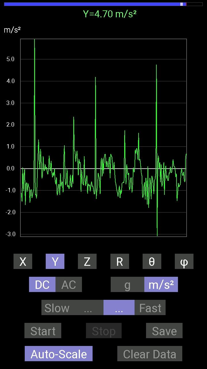
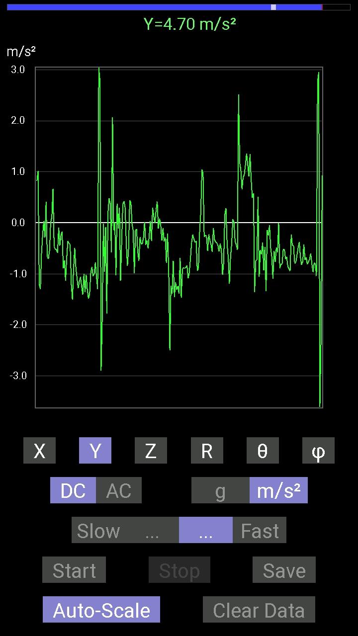
It is still an ugly “Frankenstein” of a machine, but I will post pictures as it becomes something to look at! The good news is that even though it is still in the earliest stage of development it is already making pounds of thrust (too bad NASA)! With one wheel! With one weight!
Sorry I don’t have pics yet of the PIE 5.0…
Our web site (http://stclairtech.tech) is revamped and rebuilt with new fresh graphics and a much nicer interface which is easy to navigate. I also have a page showing some pictures of UAPs (UFOs) over the St. Lawrence River on the US & Canadian border. The pics show black, odd-shaped objects in the air which might be explained away as birds or insects, but they are 100% real photos of objects which only show up on the digital camera! These are completely invisible to the naked eye! See these photos here: http://stclairtech.tech/UAPs/
Thanks for reading and following along… Talk to you again soon!