As the PIE project continues, I am not blind to reality. There are still many shortcomings to be overcome, forces within the PIE assembly which fight themselves and therefore fight against the very purpose of the PIE. “Reversion” is “anti-propulsion” and it is the bane of all inertial propulsion systems, a primary force to be circumvented as it cannot be eliminated. In the quest for circumvention there is a relatively simple sounding answer known as “redirection”. There is a type of device which has purported to have redirected reversion with good efficiency invented by a Russian named Tolchin and redesigned by another named Shipov. Because this Tolchin/Shipov (T/S) design effectively used redirection within a narrow band of geometric proportions, and because the mechanicals of the T/S drive are less complex than that of the PIE, I have allocated a bit of time and resource to verify T/S drive operation. Assuming the device is verified, a small T/S could be used as an anti-reversion device with the PIE and with other strong impulse drives as well.
Tolchin vs. Shipov: The Tolchin drive was originally fully mechanical with a spring motor and mechanical governors and brakes to build forward momentum and then partially nullify reversion. Once Shipov came into the picture the mechanical controls were replaced with electrical controls. I believe either would be effective, but electrical is easier to adjust and modify so that is the route my experimental work is following at this time.
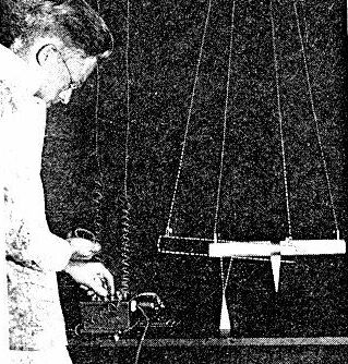
Noteworthy Difference: There is one other noteworthy difference! The Tolchin drive appears to have lacked the precision of the Shipov drive. Watching the videos of the Tolchin vs. the Shipov, Tolchin used one moveable mechanism inside another to lessen the reversion. The inside mechanism moved forward and back “pulling” the main trolly with what appear to be rubber bands. The inner mechanism may also be angled downward slightly to use gravity as an integral part of the cycle. Shipov eliminated these considerations with precise braking control of the rotating assembly.
The Tolchin/Shipov drive cycle explained:
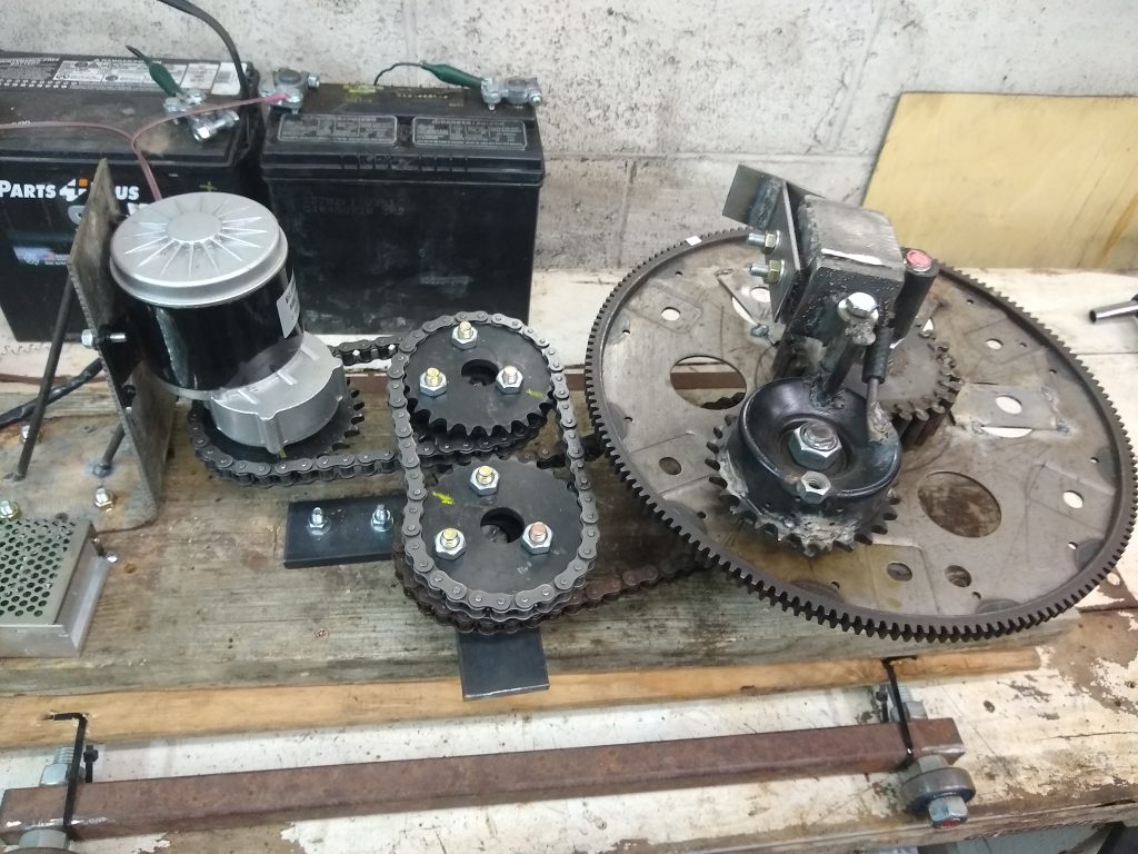
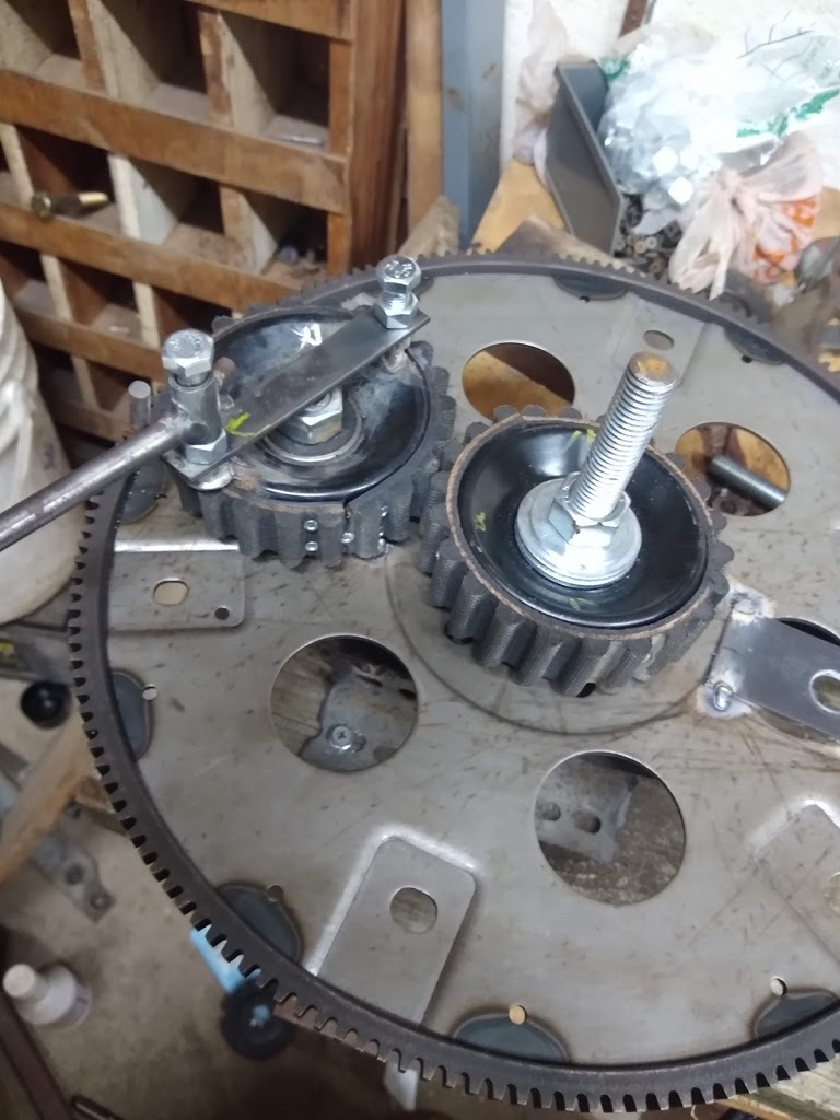
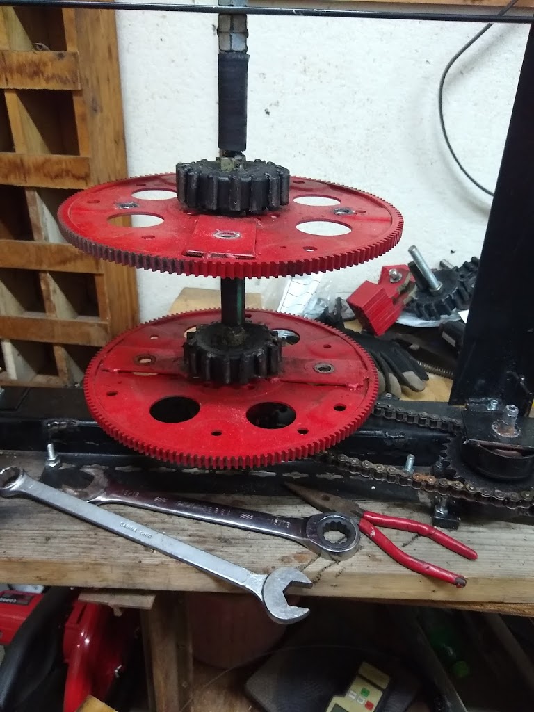
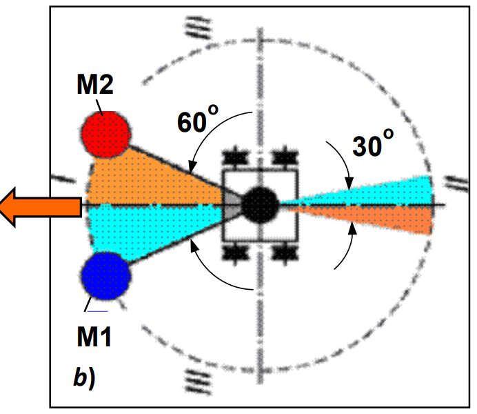
The T/S drive has 2 halves and they are identical mirror images of each other so I will only focus on 1/2 of the drive. I will be using clock positions of the weights for clarity. The rotation in this explanation will be clockwise to follow the numbers and 12 o’clock is straight forward.
1: At 12 the weight is moving at base speed.
2: At 1:30 (60 degrees) the weight is accelerated to approximately 2X to 3X the base speed (power stroke).
3: At 5:30 (30 degrees from center measured at the bottom) the weight returns to base speed.
4: The weight continues at base speed on around to 12 and starts over.
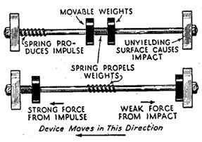
Since the acceleration force is designed to occur within a 90-degree arc (1/4 revolution), the forward thrust needs to be more than the reverse thrust used in returning the weights to the front. This is simple but stopping the acceleration (accelerated speed) at the exact right moment is critical if the T/S drive is to function!
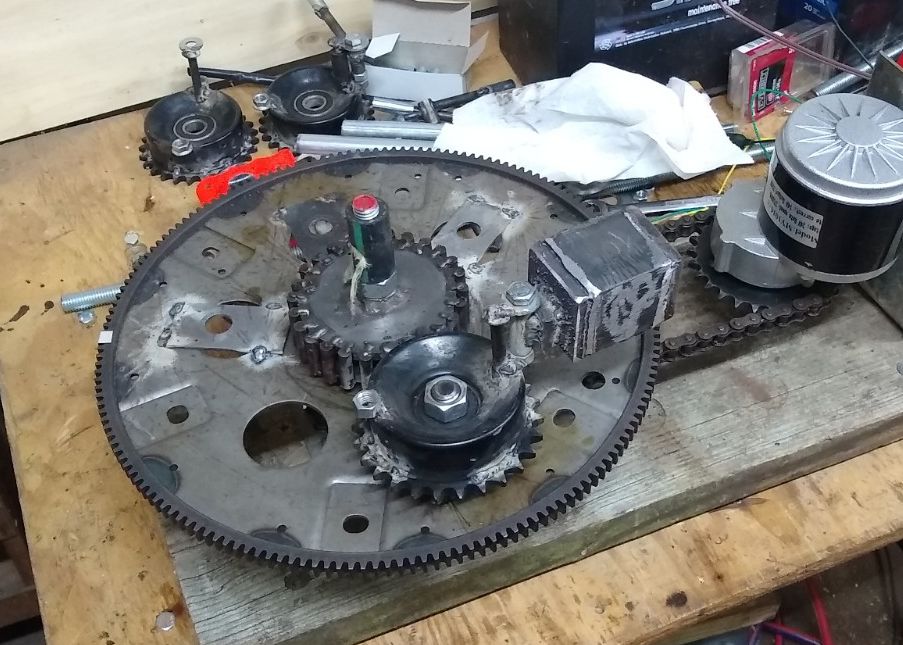
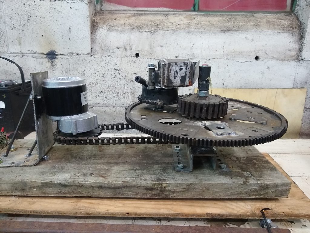
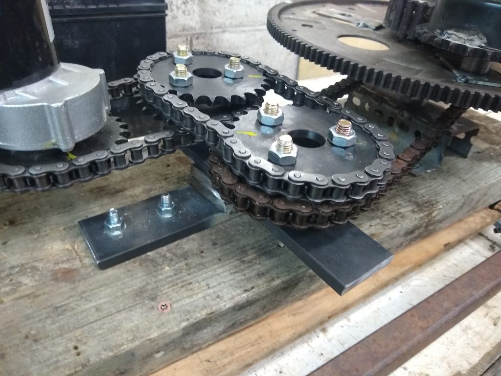
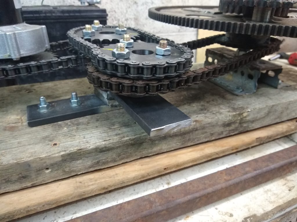
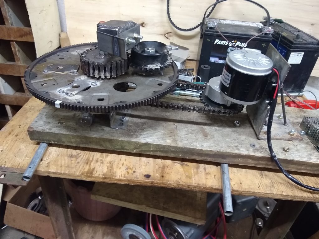
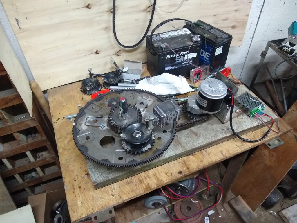
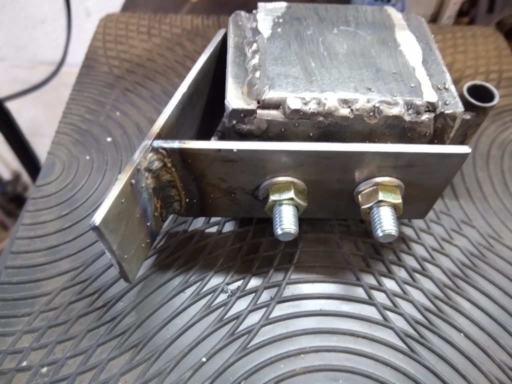
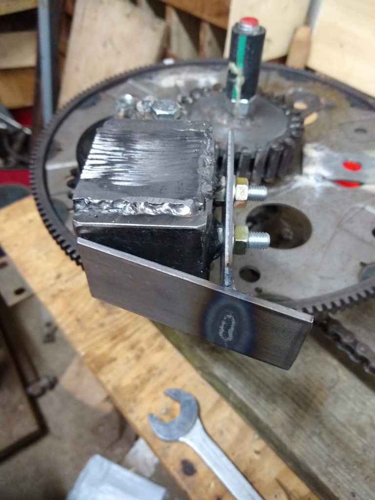
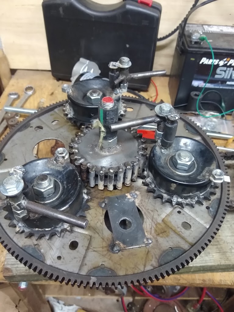
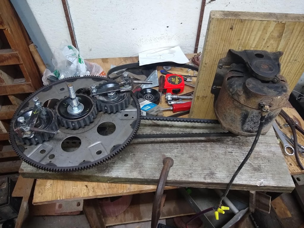
Current: Right now, the gearing is put together and I am currently powering it with an obsolete cordless drill mechanism. Speed control is accomplished with the same controller being used on the PIE 4.7, including the SDC control.
Problem: The problem with my replica is the weight’s return to base speed is not instant, and because the rotation is still moving too fast (and overshoots the desired slow-down position) the centripetal force pulls in the wrong direction. A brake is needed to quickly (instantly if possible) slow the rotation speed back to base speed. I believe this might be accomplished with a “motor brake” working similarly to a modern cordless drill which stops without coasting when the trigger is released. Another thought is that my weights are too heavy for the older model drill motor to effectively decelerate quickly, and they may need to be replaced with lighter weights.
Gyro, Centrifugal, Centripetal? Shipov called this a “4D gyroscope” where the 4th dimension is time (rotation speed), but it could also be called a “centripetal drive” since thrust is derived by accelerating the weights in an arc toward the rear, and then the centripetal energy is absorbed by reducing speed at the moment the direction is perpendicular to desired motion. Since the mirrored half is doing the same thing in the opposite direction, sideways force is cancelled at both the acceleration point and deceleration point.