I apologize for the time lag since my last posting, life tends to get in its own way sometimes but we all do what we have to do.
Website & Manual: I am building a website for my little consulting firm focusing on the R&D side as well as the PIETECH manual (basically complete, getting finishing touches now). There will also be access to companion videos. That access will only be available with the purchase of a manual. The address to the website is http://www.stclairtech.techit is online now but I hope to have it truly functional in the next 3 weeks.
At this point in time, the manual (and its companion videos) will be the only information that is not completely free. This will hopefully help offset some of those constantly inflating costs.
A Kit?: Another possibility which came to me as a suggestion is that of a functioning miniature model kit. The kit may be a partially assembled, or only contain the finished pieces. That idea is still only on the drawing board for now until the logistics can be fully worked out.
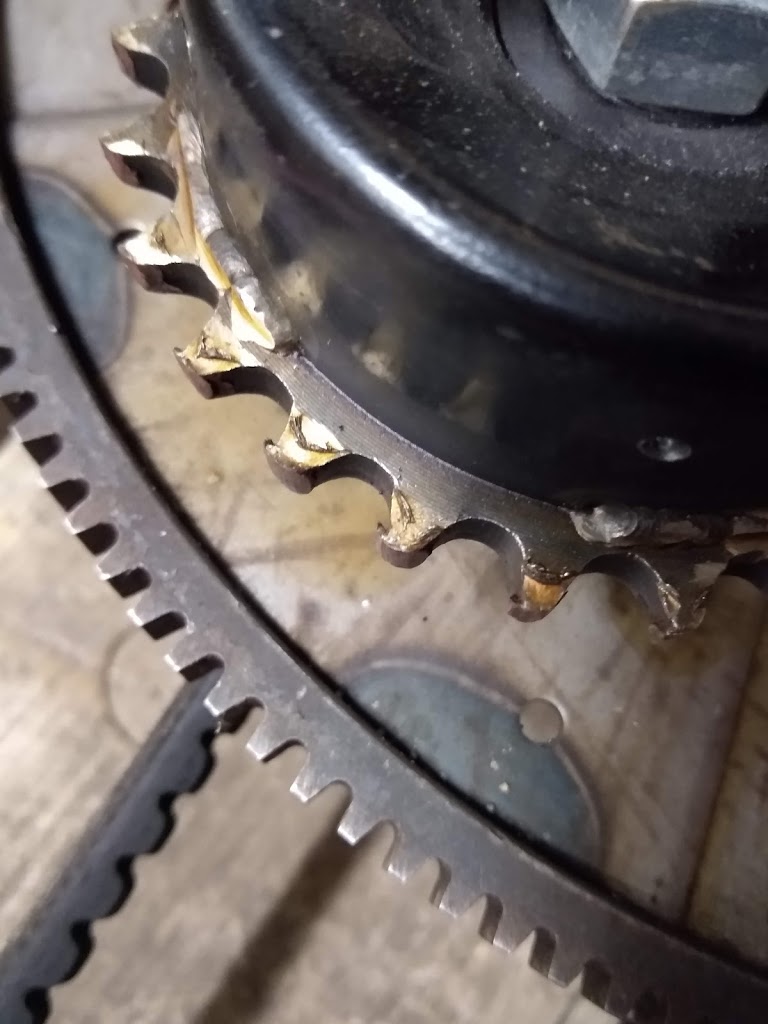
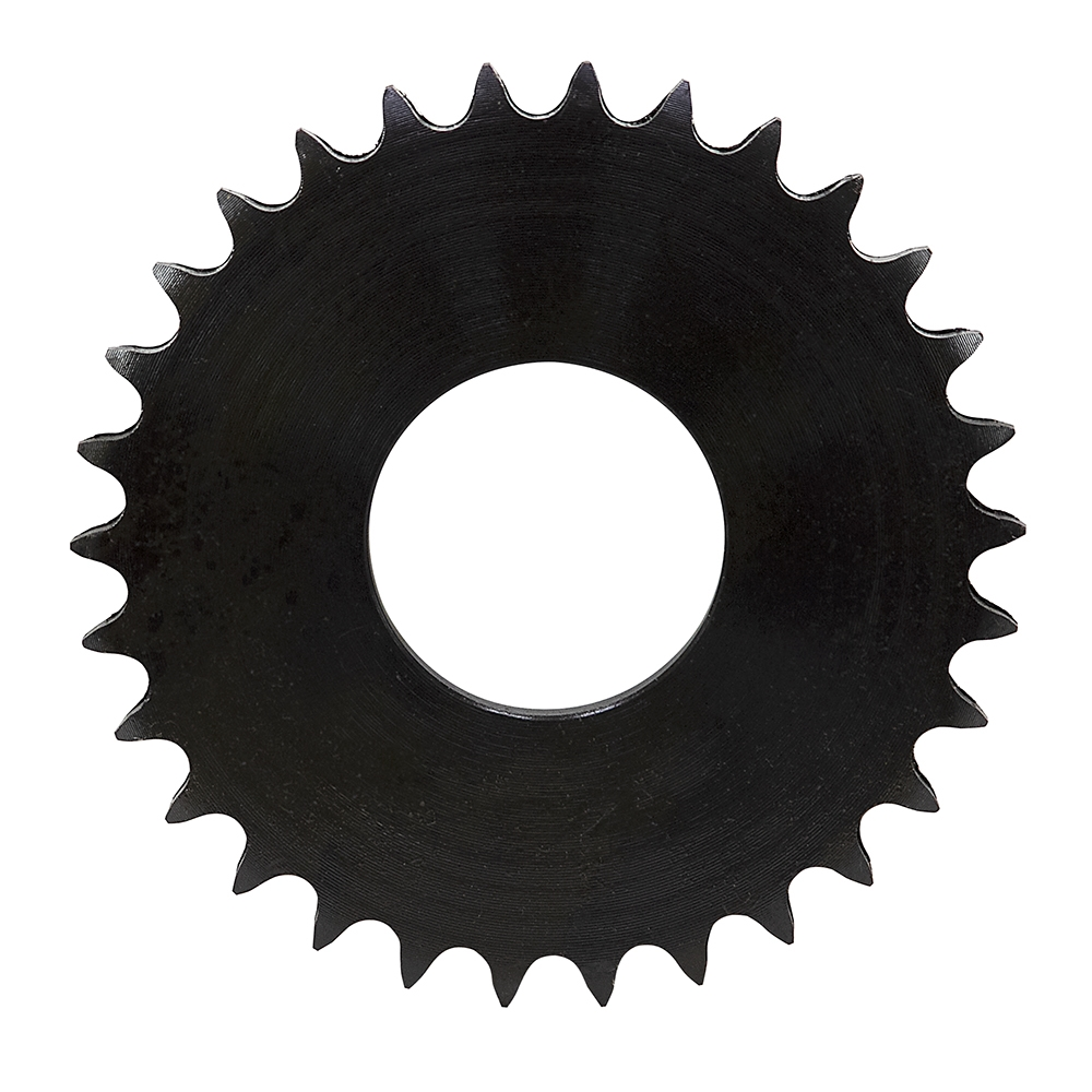
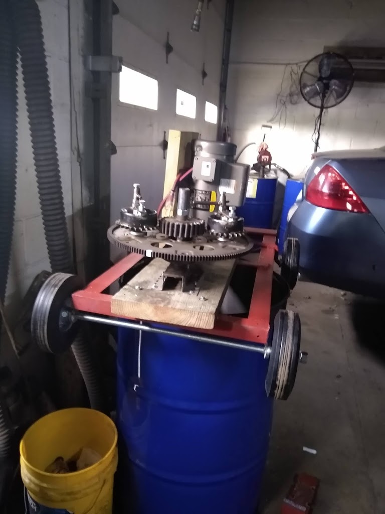
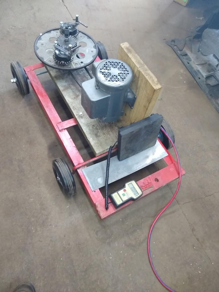
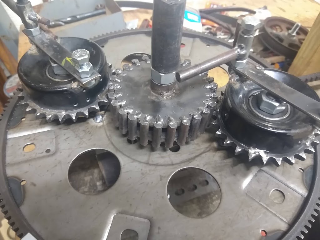
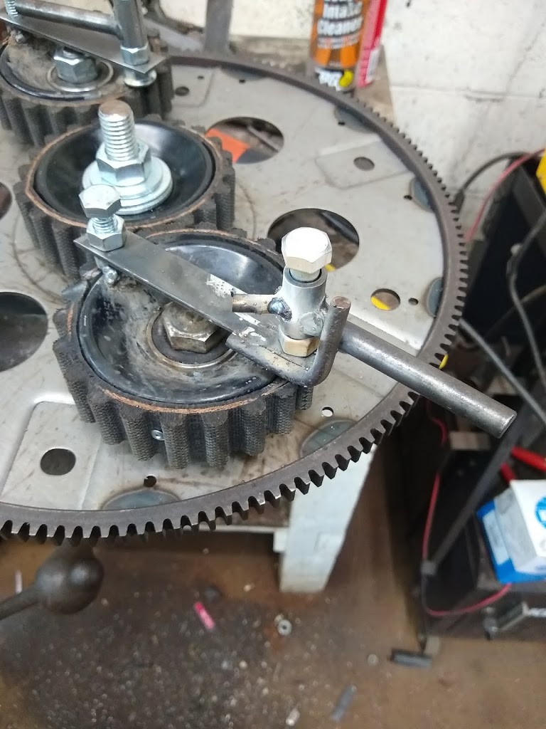
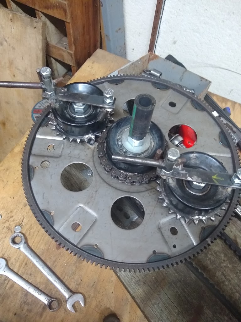
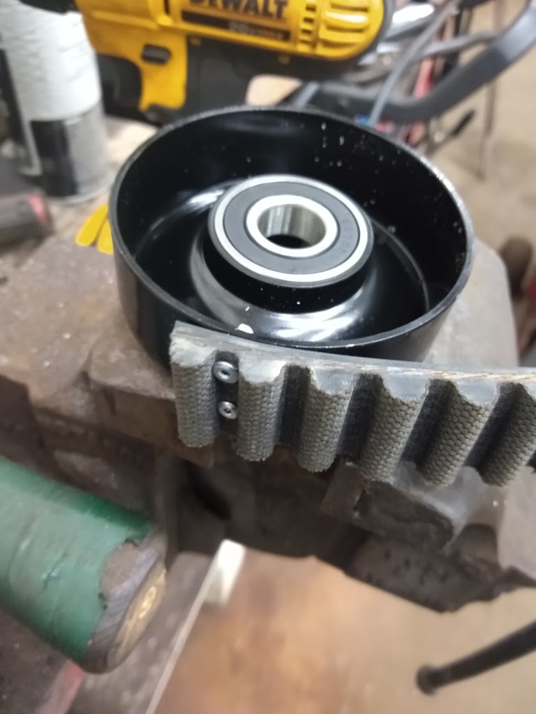
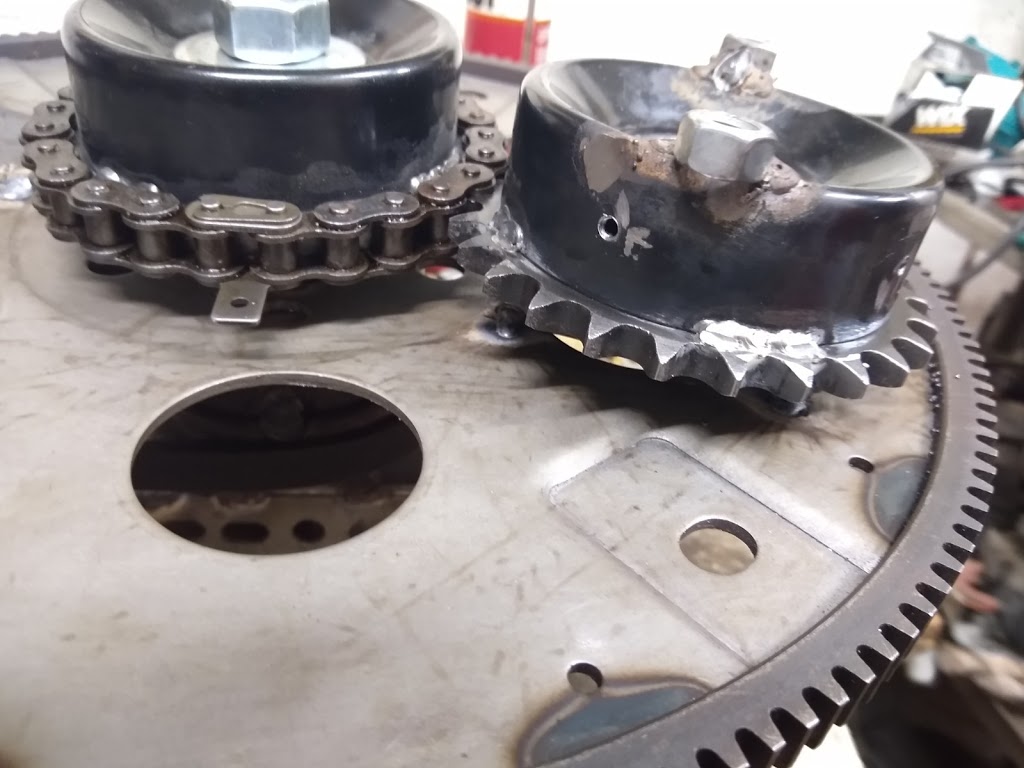
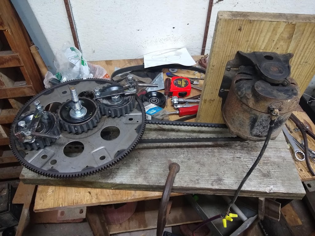
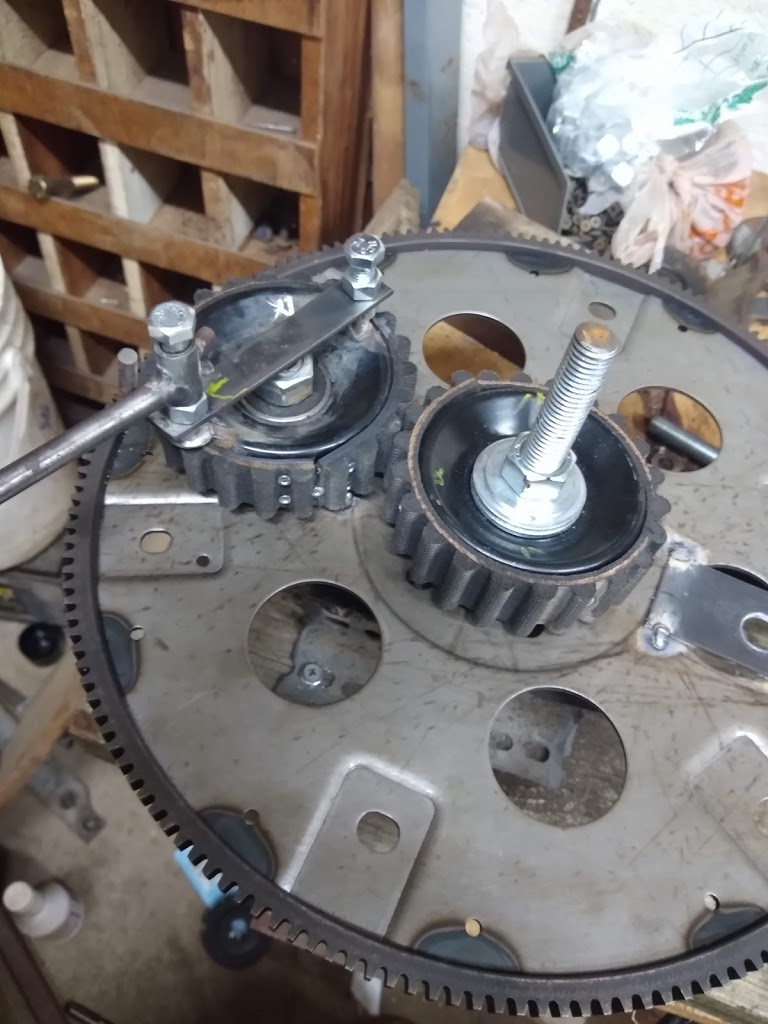
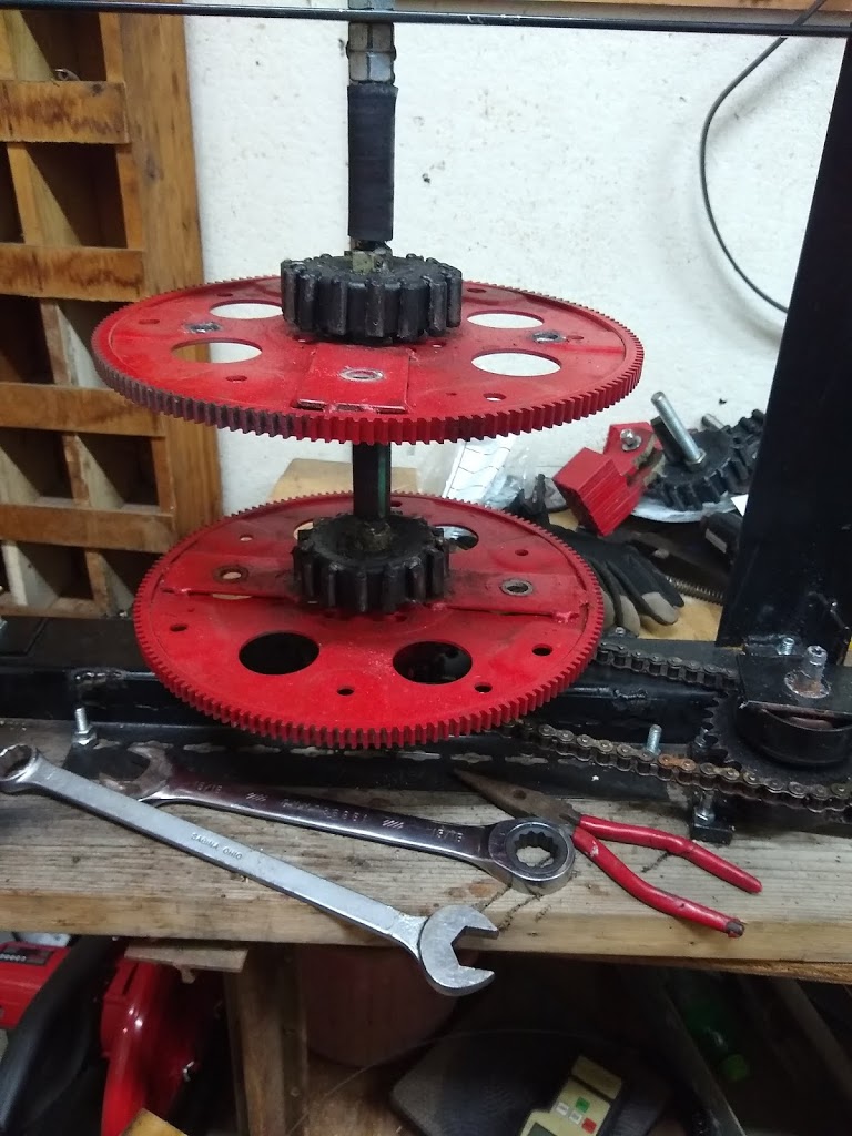
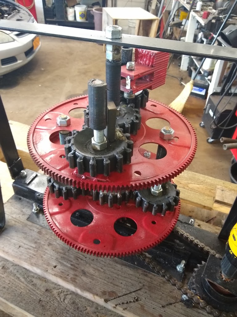
PIE 4.3 Current Progress: I have taken the PIE 4.3 apart to replace the drive pulley with a chain sprocket. This has given me the opportunity to analyze the unit looking for weaknesses and damage.
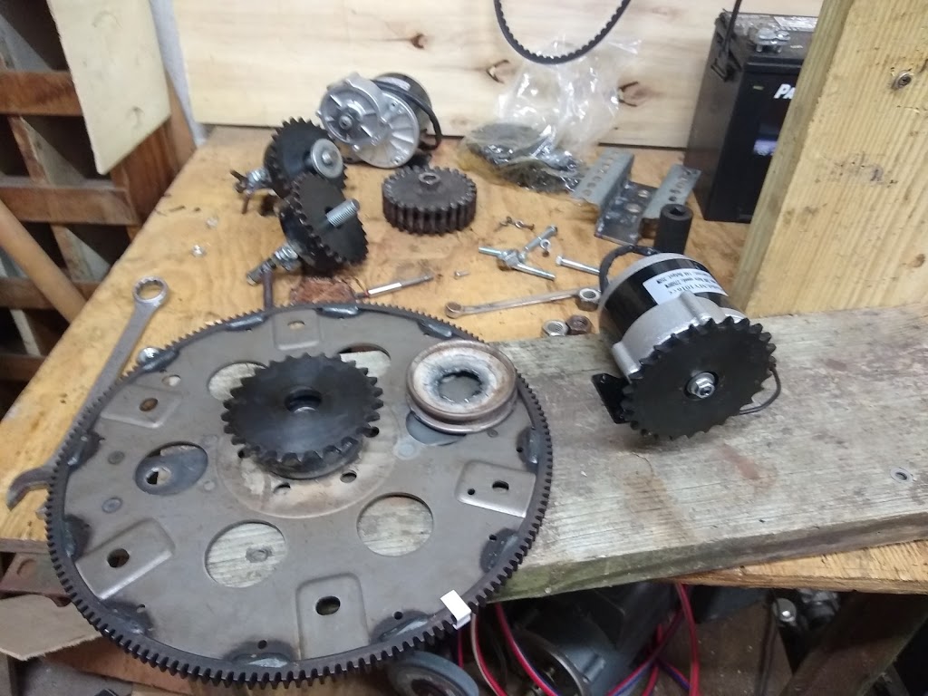 |
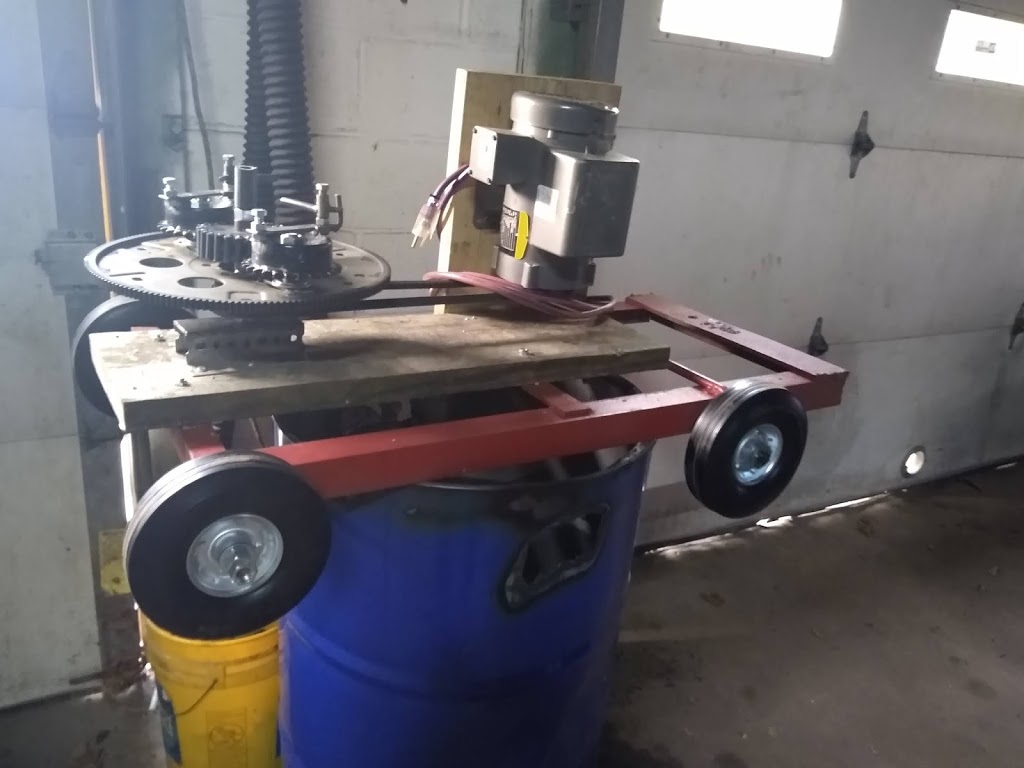
| Disassembled PIE 4.3 |
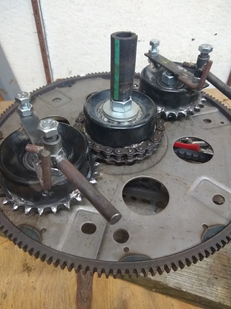
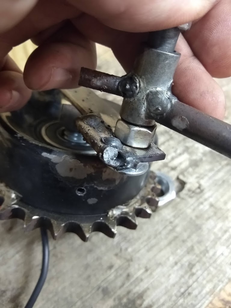 |
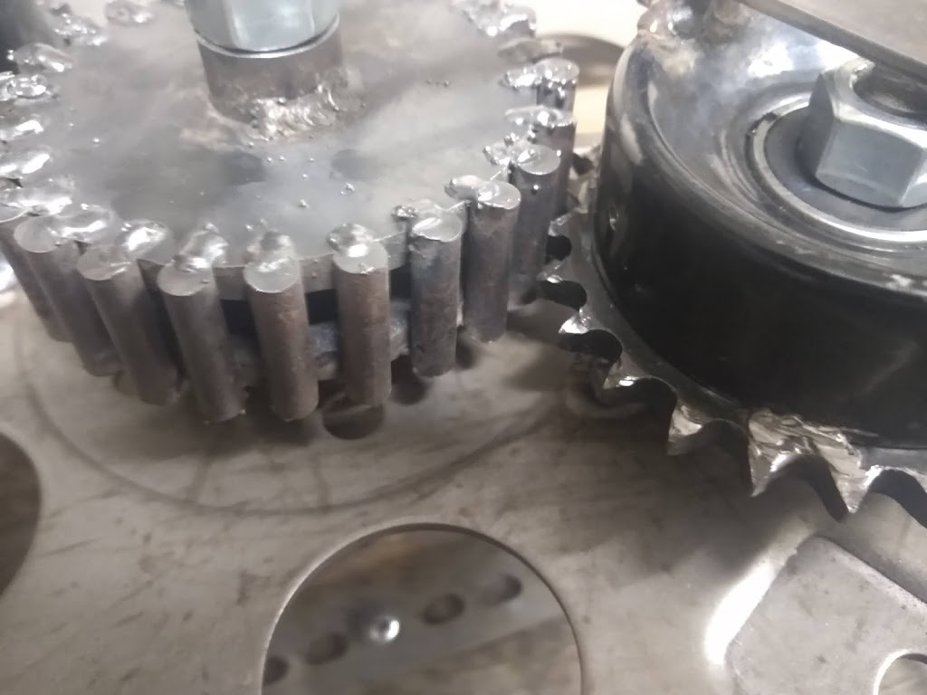
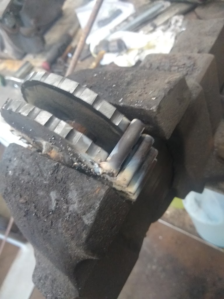
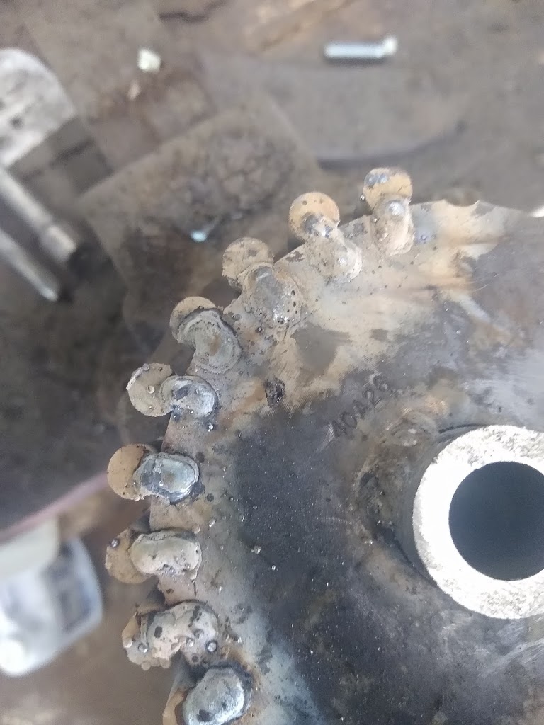
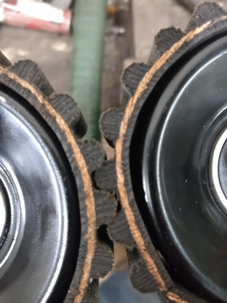
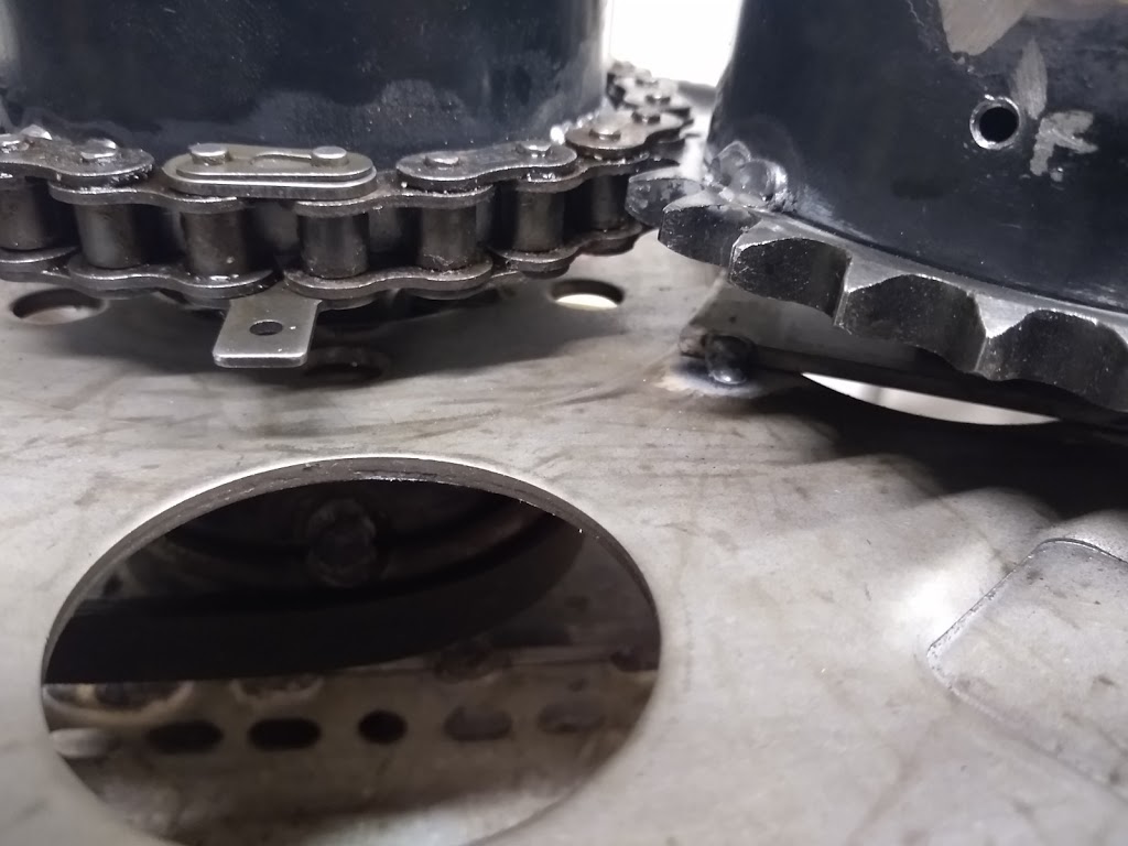
| Broken Outer Stop |
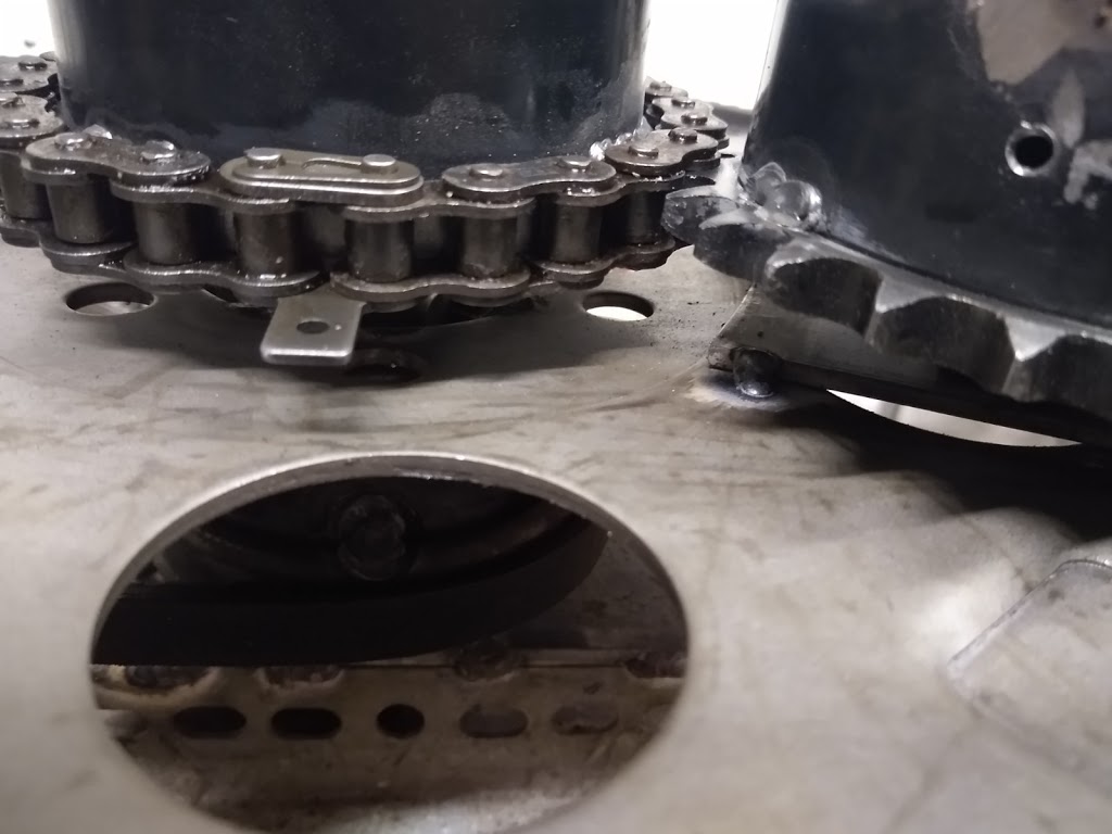
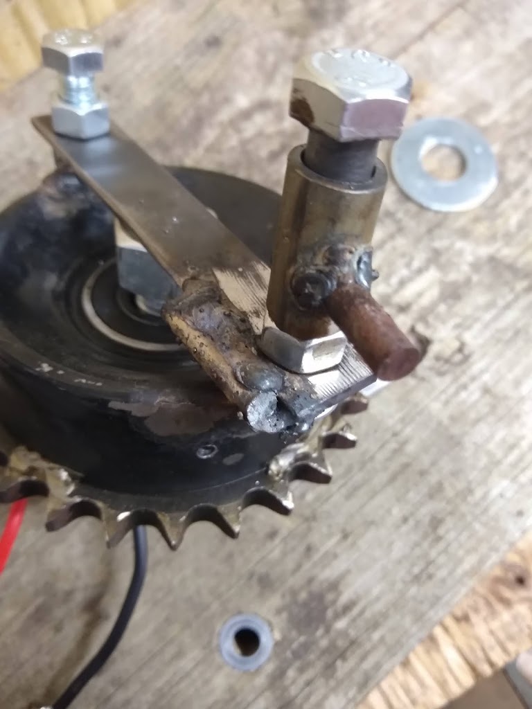 |
| Broken Outer Stop |
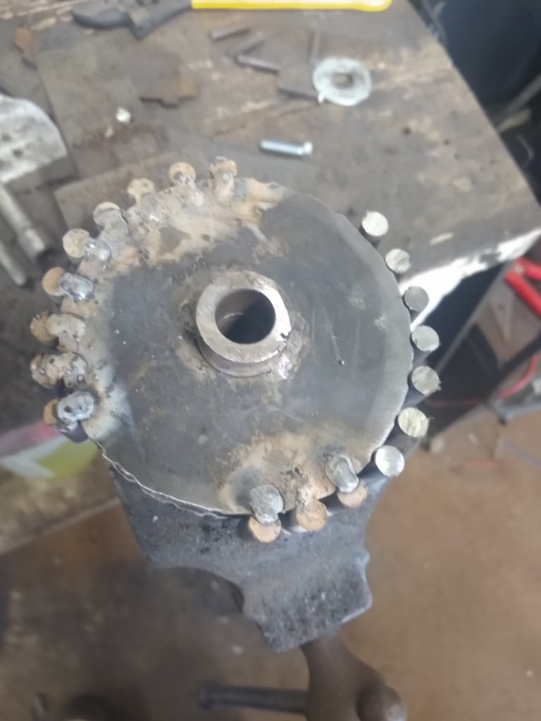
It is very apparent that the outer stops were the first weak point, and once they would break there was a cascade effect of failures. The weight would, at times, be allowed to collide end first into the inner stop (sun gear axle). This caused enough deflection in the wheel and axle that the planet gear could skip a few teeth and become “out of time” with the assembly. Now that the 4.3 is apart I have found that the wheel is slightly bent (about 3mm or 1/8”) which is not enough to need replacing yet. The axle is also bent, and that is now definitely scrap metal, There are vides posted to YouTube and BitChute describing the process and showing the bent axle.
YouTube: https://youtu.be/wmoc2-1v43A
BitChute: https://www.bitchute.com/video/rfK5qGGRDffR/
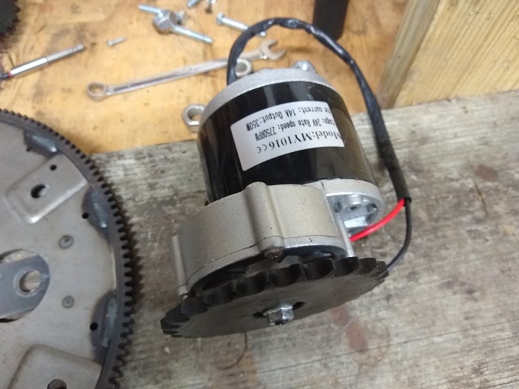
I have also received 2 new gear-motors for the PIE 4.3 which are all set up to run at approximately 300 RPMs at 24 volts DC. I am seriously considering running 2 wheels, each with their own drive motor. That may be overkill, but right now design simplicity is very important for the purpose of easy transitioning into the testing phase.
It is reasonably simple to set up a chain drive that would spin the wheels in opposite directions (obviously planning opposing wheels) and they would obviously always be in-sync with each other, but there are other testing considerations like running wheels at different speeds and easily being able to reverse either wheel’s rotation.