12/23/20 PIETECH Page 11, PIE 4.6 Eccentric Drive Gearing
I was going to be putting my effort into duplicating the dead blow weight so that I can test the first wheel with 2 weights, and I can build a second wheel to go with the first one. However, when I was doing the propulsion testing with the single wheel, I noticed that as by battery started running down propulsion was diminishing. This was found to be a “slow-down” of the motor during the critical “power-stroke” (those who have read my manual know what that means) causing propulsion loss. To compensate, I manually turned the knob on the speed controller during slow speed operation. Naturally, I did not meet the correct RPM every time, but I noticed that if I overshot the running RPM at exactly the right moment, the PIE 4.6 would lurch forward much stronger.
A friend of mine, who also has been working on his own inertial propulsion drive (YouTube Channel) and I were discussing this. It has been found that changing the time base in mid or quarter turns of the main wheel could enhance the propulsion effect dramatically.
My choices for this concept are to either electrically change the RPMs back and forth or use eccentric gearing to smoothly transition the RPMs thus changing the time base. In the end I may try them both or perhaps someone could find a better method.
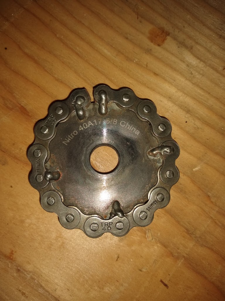
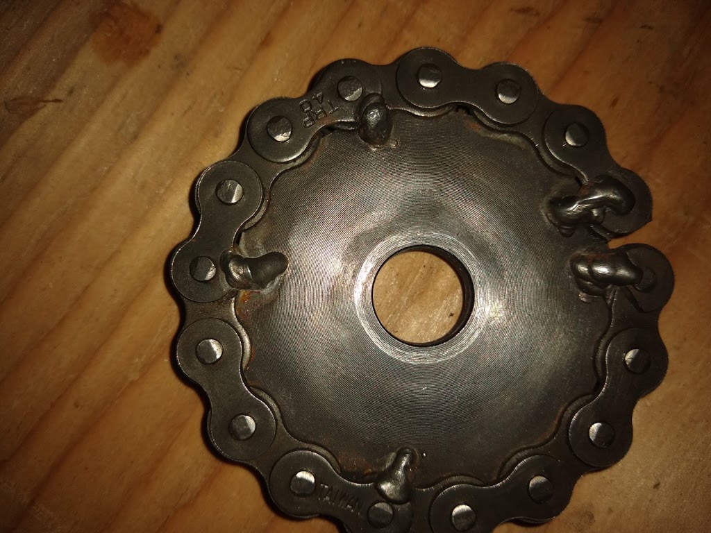
For now, I have started this experiment with the eccentric gear setup. Eccentric gears are essentially a pair (or more) of identical gears or sprockets, with their axle’s not on center in the exact same amount. Since each will “wobble” exactly the same amount, they can be meshed together. When one it rotated at a steady RPM by an outside source (electric motor, etc.) the other one accelerates through half of its rotation and decelerates through the other half.
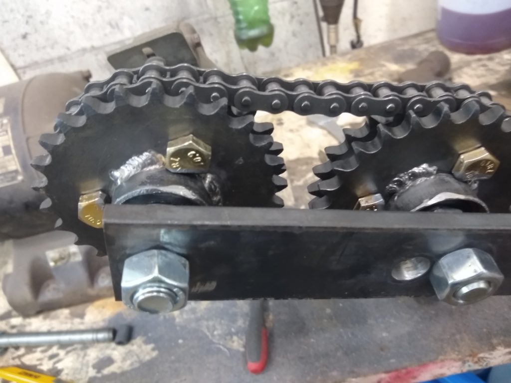
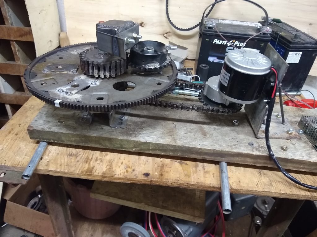
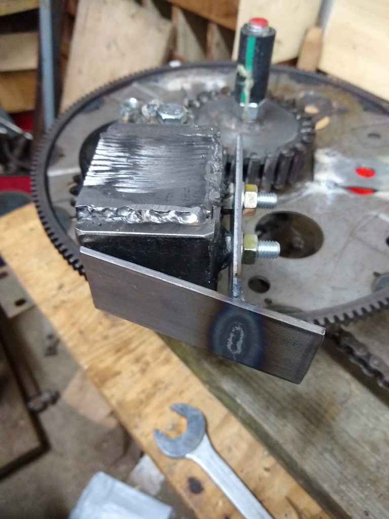
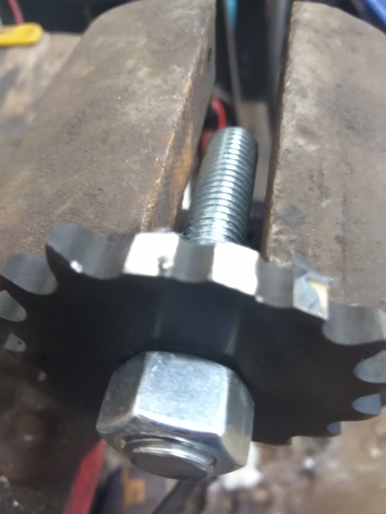
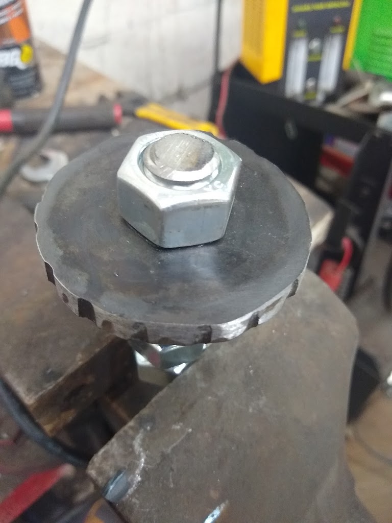
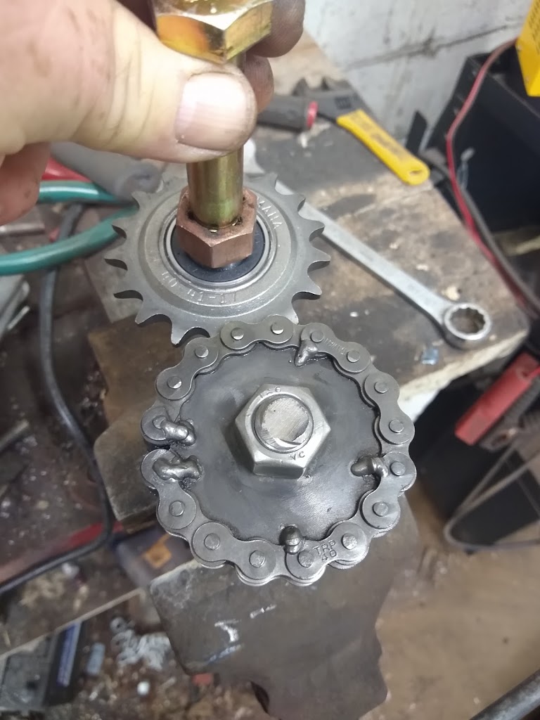
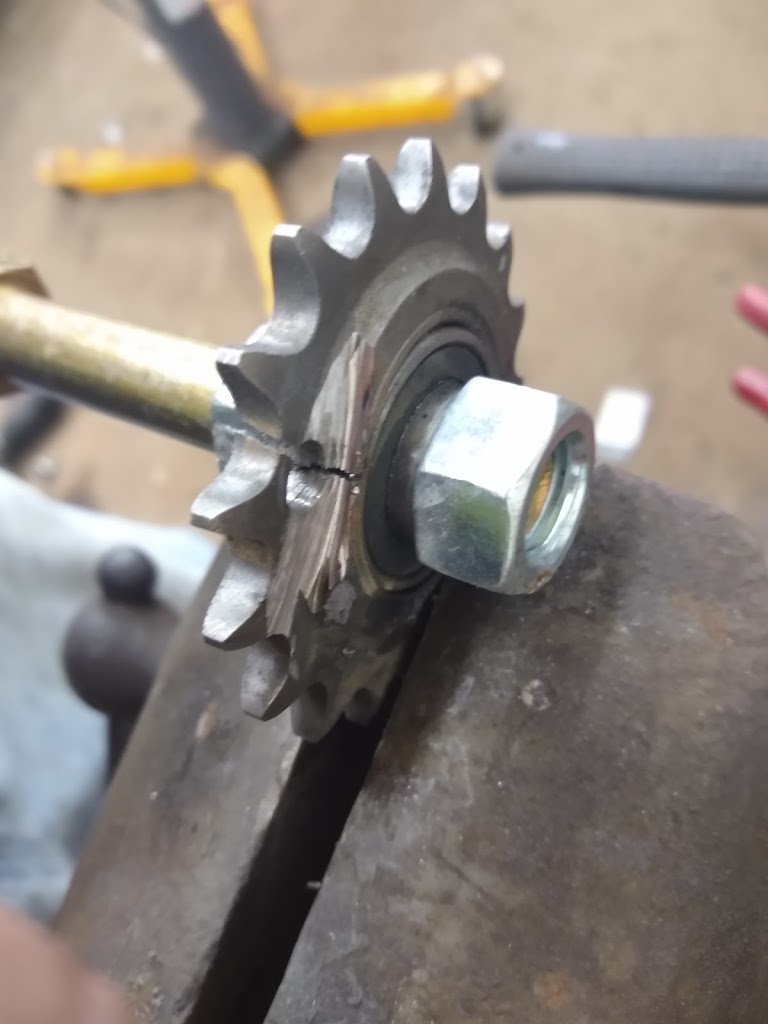
So, for my experiment I have 2 identical sprockets, each mounted on-center and each on a bearing. Then there are two more identical sprockets fastened parallel with the first ones, each mounted exactly the same amount off-center. The two off-center (or eccentric) sprockets are timed and connected together with roller chain.
Sprocket set 1 is driven by the electric motor. Sprocket set 2 is connected to the PIE 4.6 wheel. As the motor turns at a steady RPM, the PIE 4.6 is accelerating and decelerating constantly. This is timed to start the acceleration approximately halfway through the portion of the cycle when the weight is in contact with the center (inner stop) axle. Timing here is very important and even a few teeth off on the sprocket to wheel timing makes a huge difference. In fact, it has been observed that with the timing off too much, the unit would oscillate forward AND back with significant force.
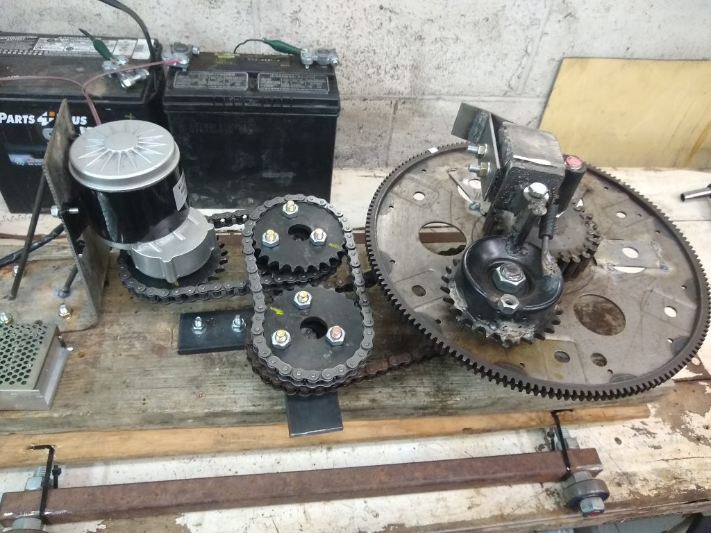
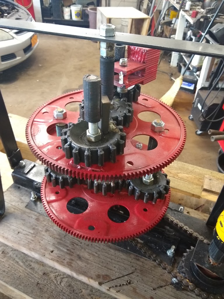
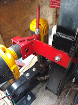
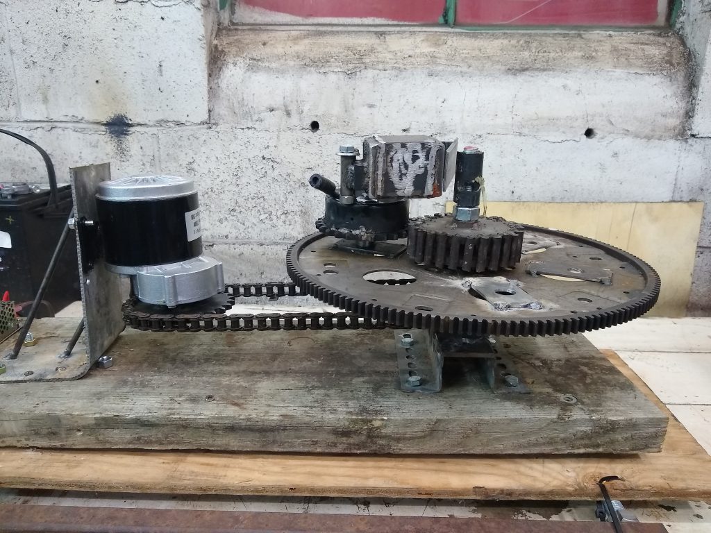
Eccentric Drive Ready For Testing (Timing Was Not Correct In Picture)
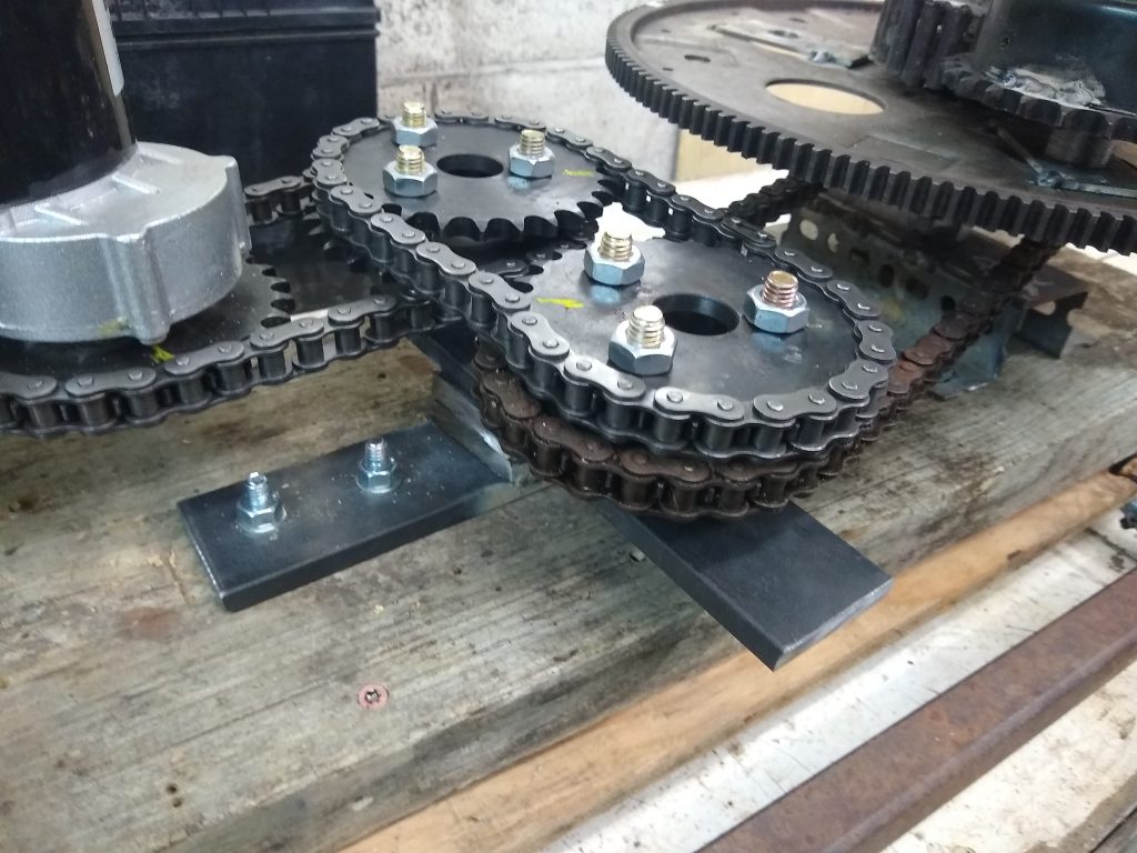
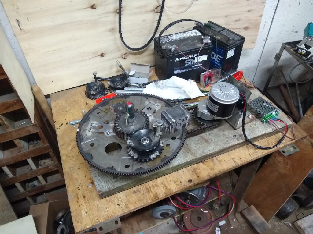
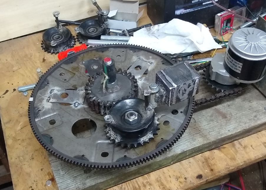
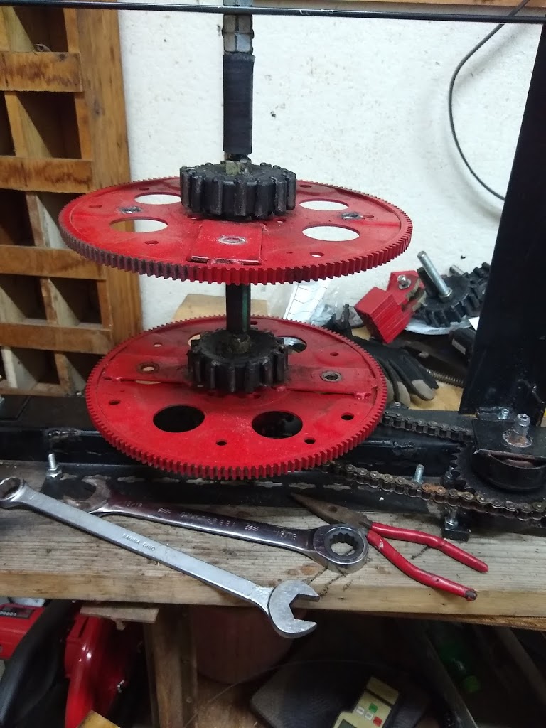
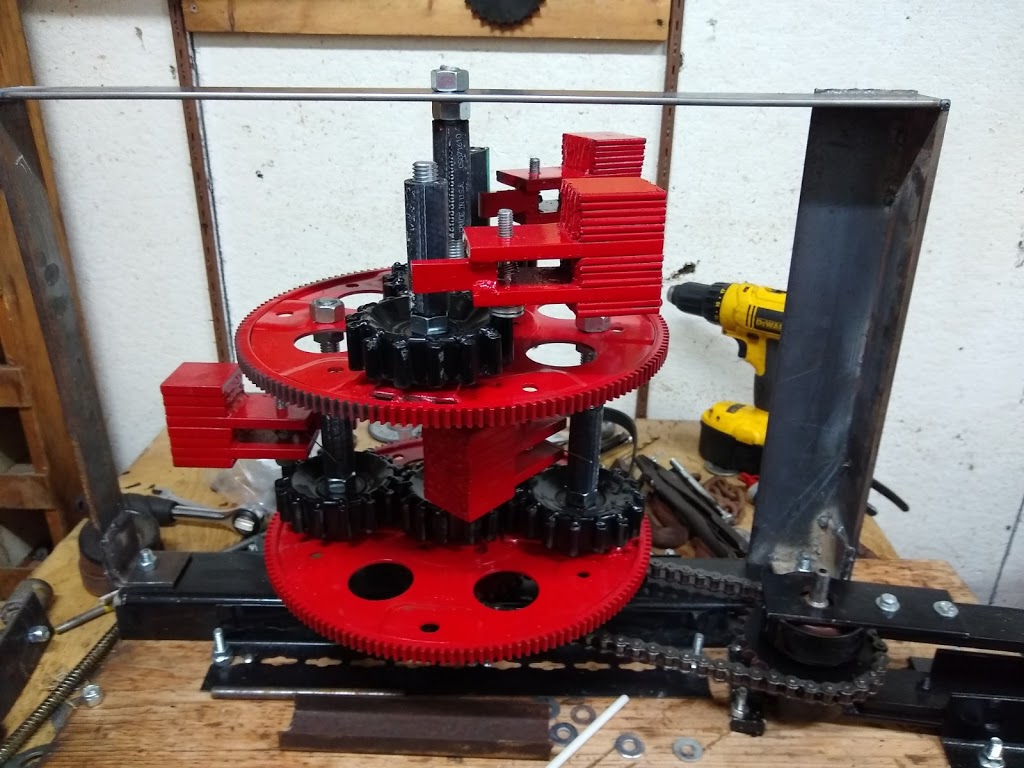
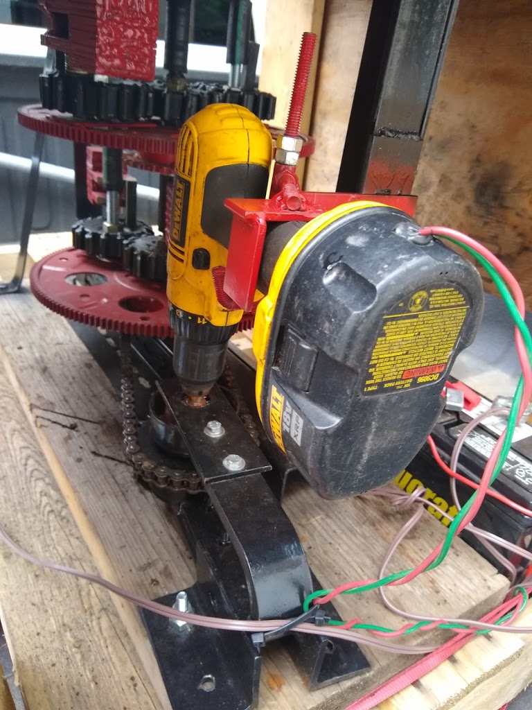
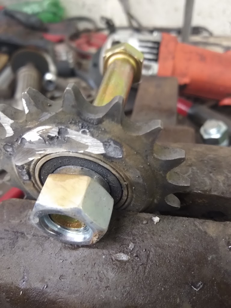
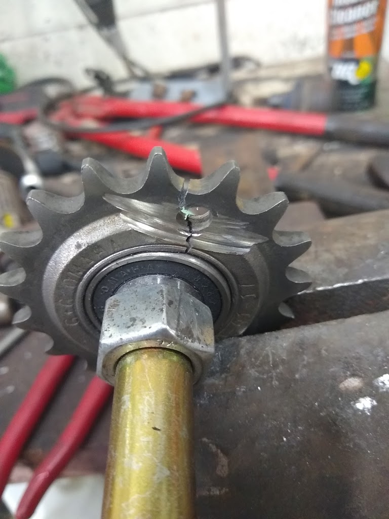
Eccentric Drive Testing (Yellow Marks are for Timing Reference)
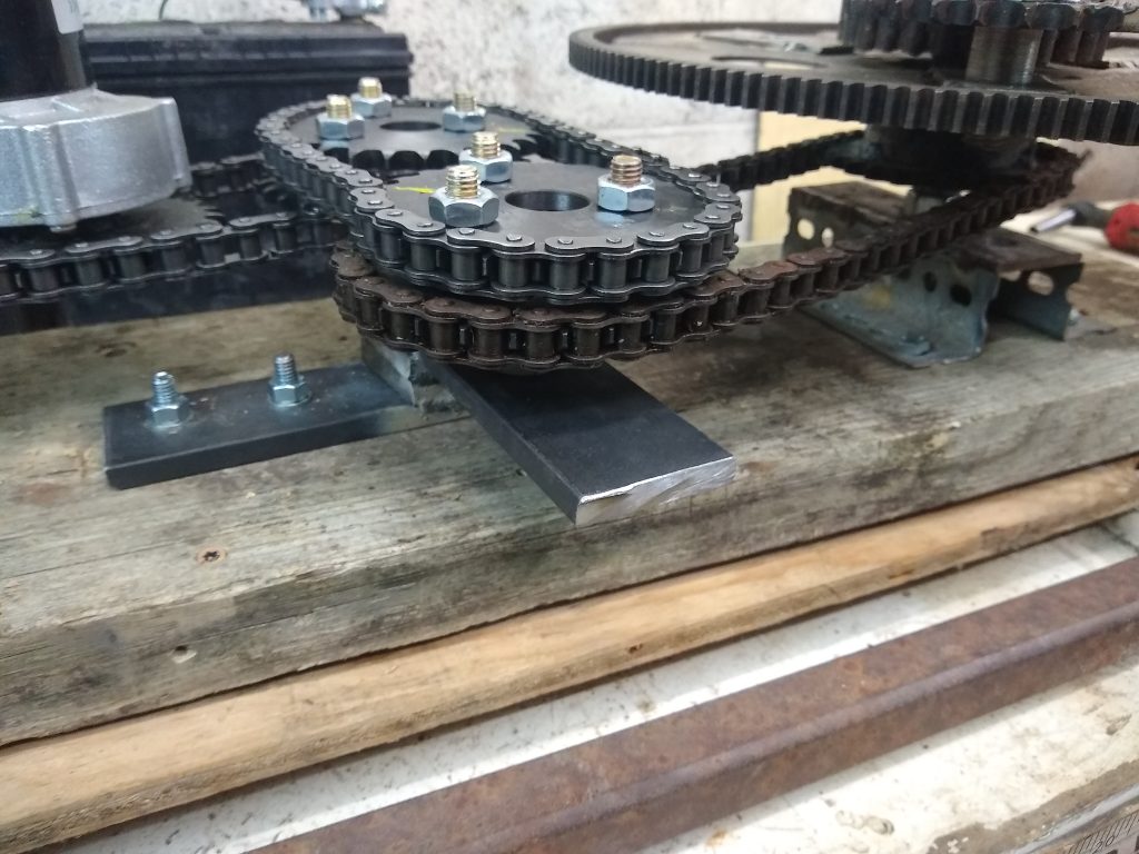
Eccentric Drive Testing (Yellow Marks are for Timing Reference)
I know that this design will not be well suited to having multiple weights on the wheel, but I do have a goal in mind that I am not ready to introduce just yet. If this idea works out, it would be capable of enhancing the operation of any of the PIE versions.
The downside is; if I only have 1 weight per wheel the RPM is limited due to transverse (sideways) forces threatening to tear it apart.