It has been a while since my last update. I guess I kind of went down a bit of a rabbit hole looking for answers to the reversion issues that virtually all inertial drives have. The answers I found are useful, and everything learned has value!
My search took me through the world of compound levers, offset drives and finally to the Tolchin/Shipov drive. The T/S drive taught me the most as it uses some of the same principals necessary in virtually ALL inertial drives, which is adding the 4th “D” (Dimension) to a gyroscopic arrangement.
4D Gyroscopes: Everyone (basically) learned about 3D in grade school. Height, depth and width or in machine shop geometric algebra, X, Y and Z axis or dimensions. The 4th D is T, or time. Time in a spinning gyroscope is measured in RPM, or revolutions per minute. Adding the 4th “dimension” to a gyro is done by rapidly and purposefully changing the RPM faster AND slower, generally within a single revolution.
If you were to view a conventional toy-type gyroscope, you will notice a frame surrounding the flywheel and a smooth-rimmed flywheel in the center. Now, use a marker (pencil or crayon is fine) and put one dot on the rim of the flywheel. That is now our reference point. Place the gyroscope so you can see the entire rim of the frame and the rim of the flywheel. Place a mark on the frame at the top and the bottom as you are viewing it (right and left work too) and then using your finger turn the flywheel rapidly from one mark to the next, then slowly from that mark back to the beginning. That is the 4th D!!!
Imagine spinning the flywheel at 1000 RPM but installing a mechanism that will slow it to 800 RPM for one-half of each revolution, returning it to its original velocity for the other half, and you have a 4D gyroscope!
Now replace the dot on the flywheel with a small weight, and spin it fast then slow then fast then slow with every revolution one-half of it is moving fast and one-half moving slower. It might not be exactly what you desire, but there WILL be inertial propulsion derived from that device!
It is not about shuttling weights around; it is all about changing the “time base” by rapidly changing speeds during EVERY revolution! Shuttling weights can be part of that and quite often they are, unfortunately many people believe that the weight shuttling causes propulsion, when in fact it is only a component of the gyroscope that can be time-manipulated into performing propulsive work. This can be accomplished mechanically or electrically, and although those two systems may appear fundamentally different, they are like the difference between a diesel and a gas engine, they may be “fed” fuel differently and the ignition of that fuel is done differently they are still a piston & crankshaft engine (there are also rotary and turbine but I’m not going there right now).
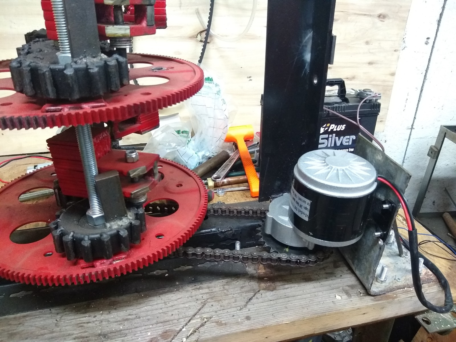
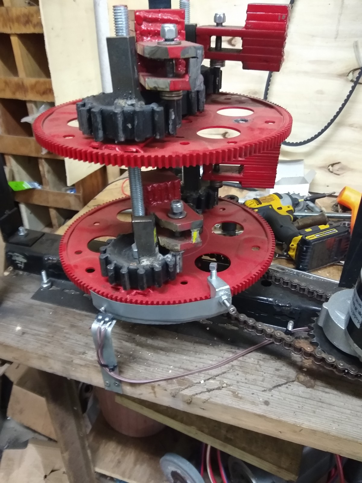
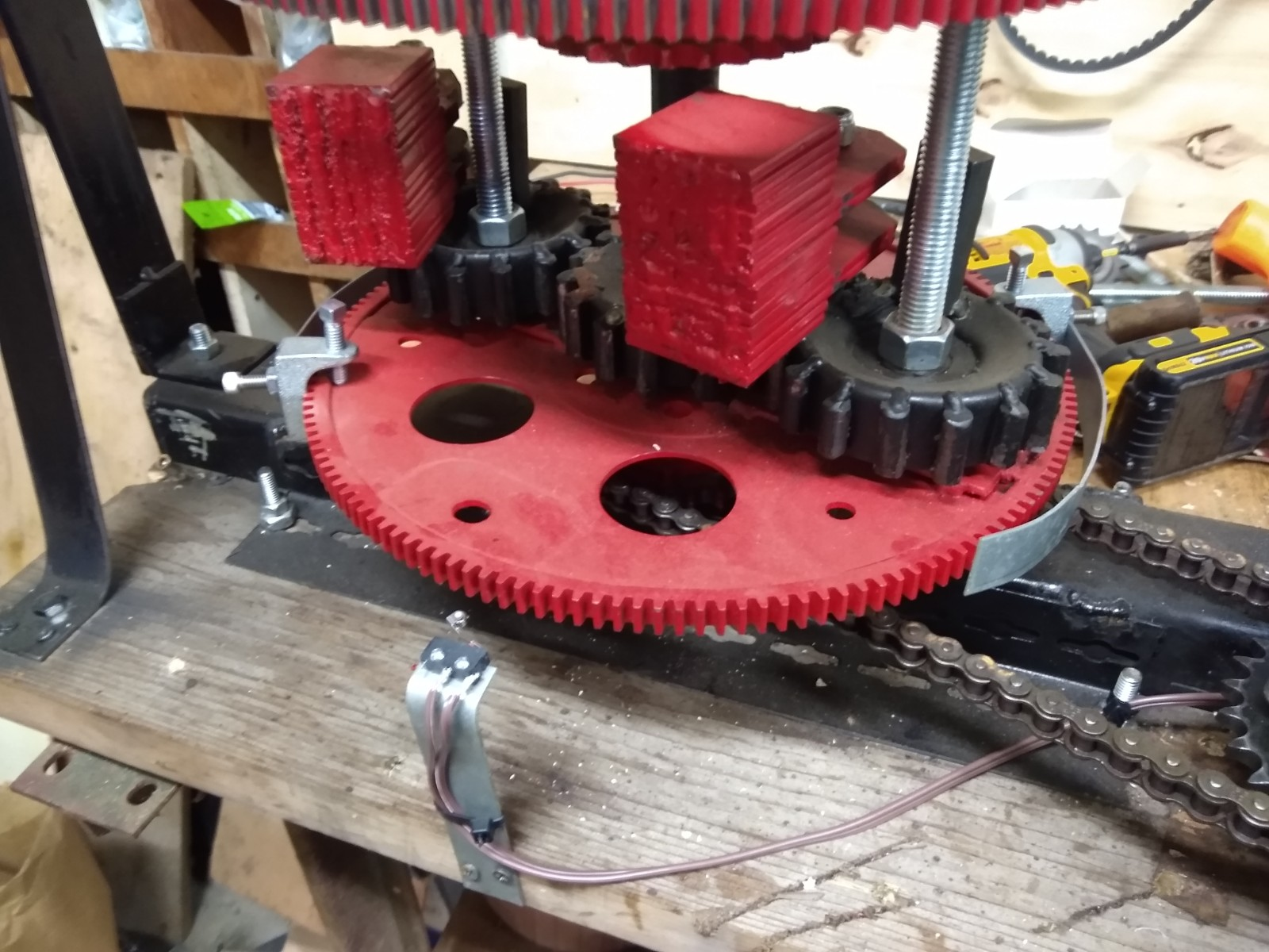
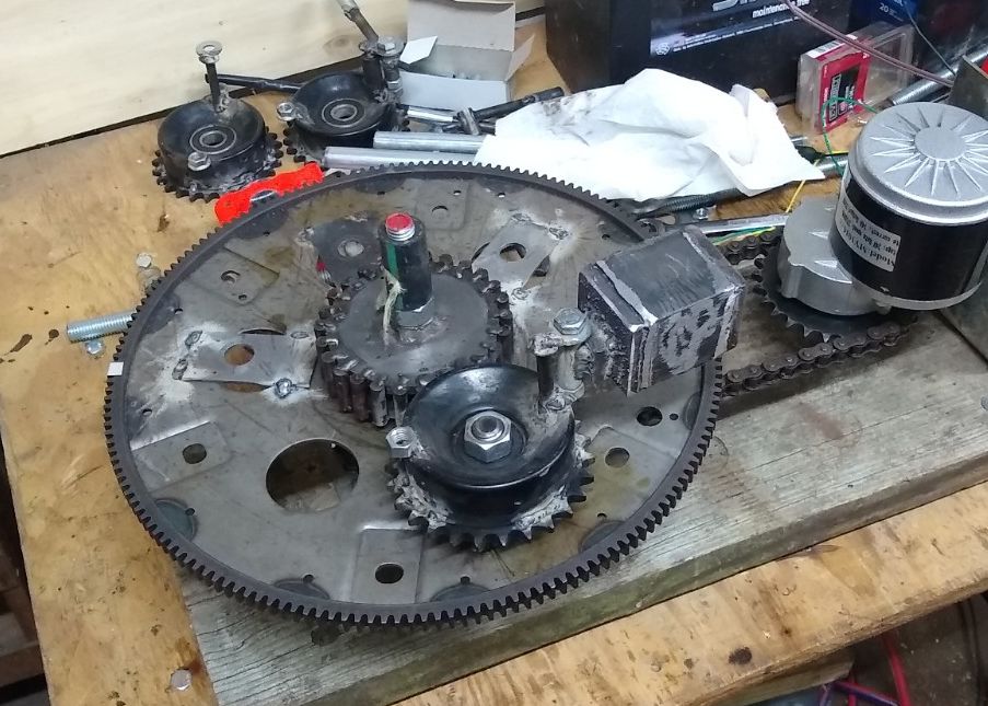
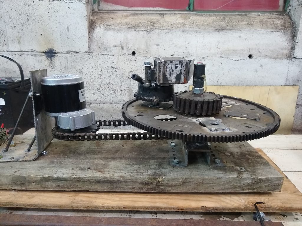
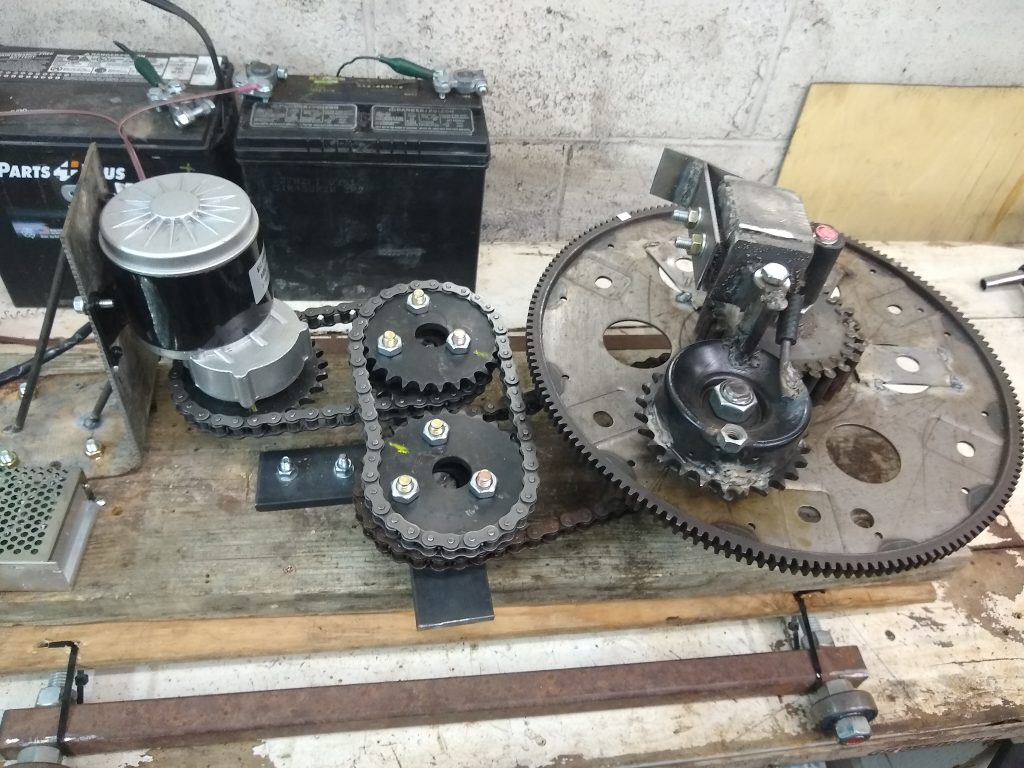
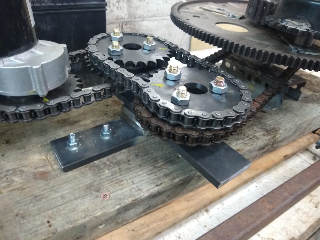
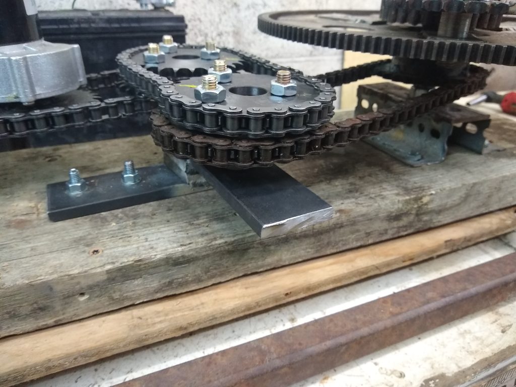
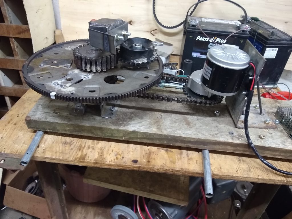
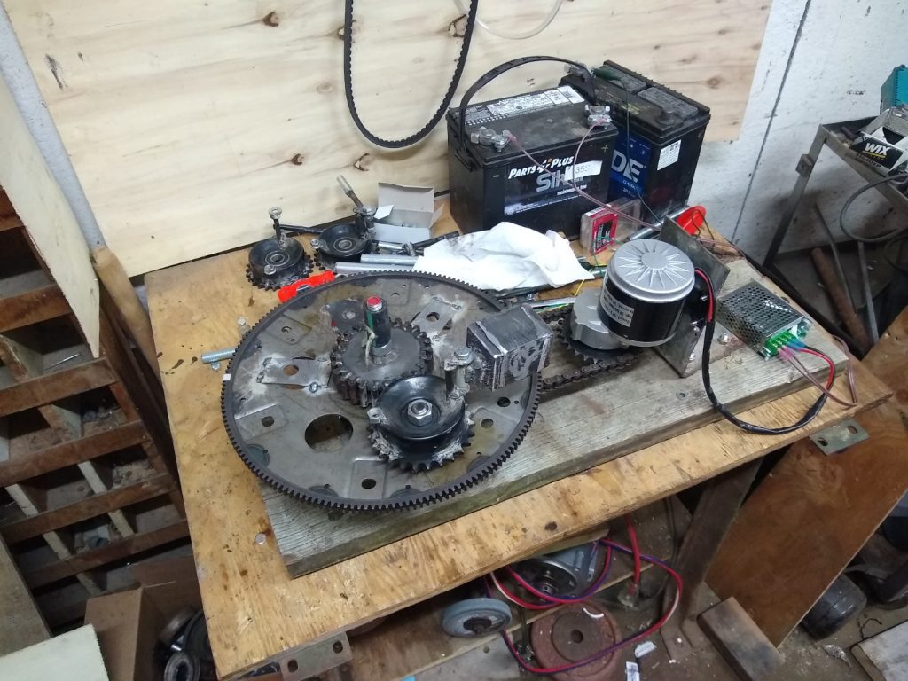
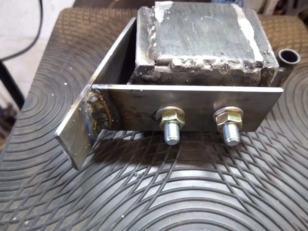
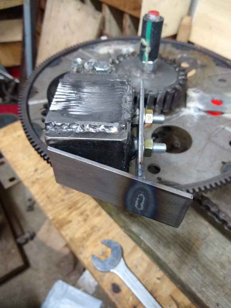
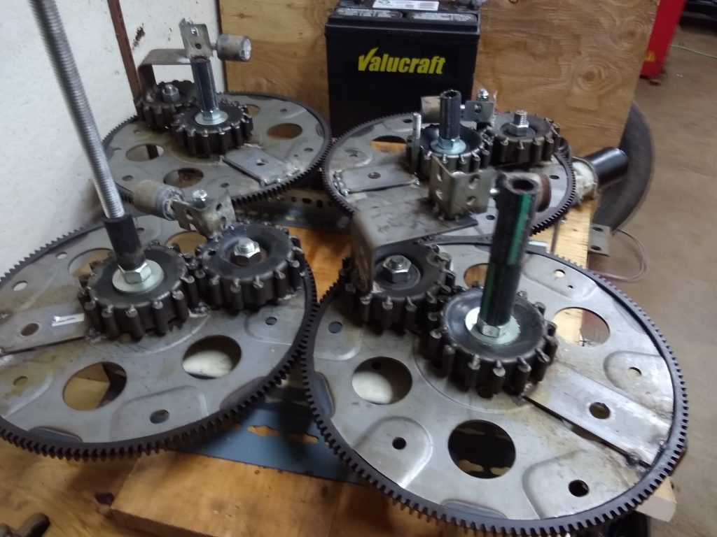
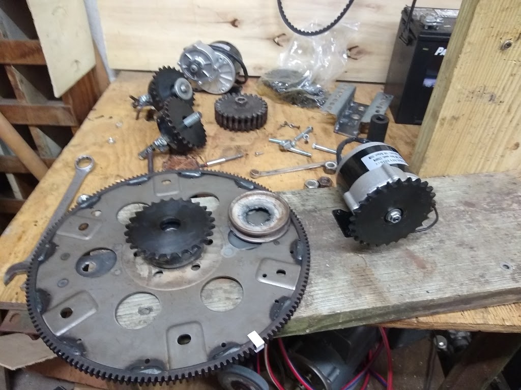
So, keeping in mind that there are different ways of accomplishing the same basic task, I am back to the PIE 4.7 with a renewed outlook and it is definitely time to “Git ‘Er Done”!