***Note #1: This post was created before P.15 so the testing spoken of has been completed already. Read PIETECH P.15 for explanation.***
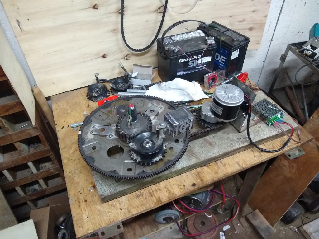
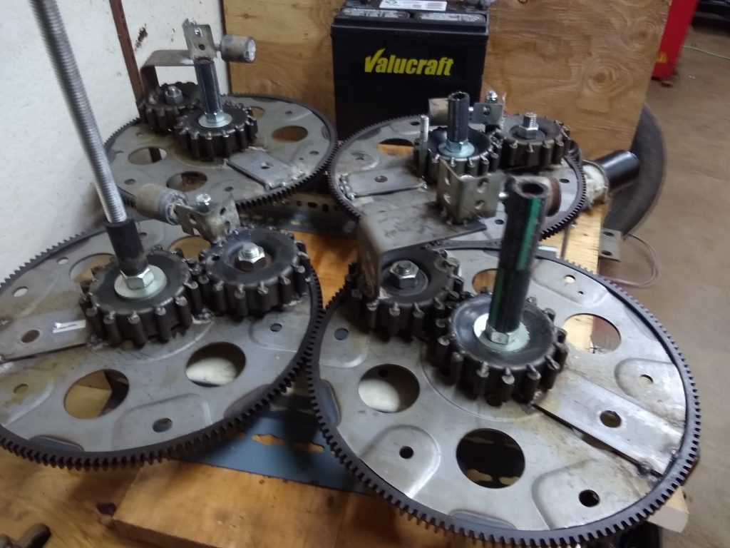
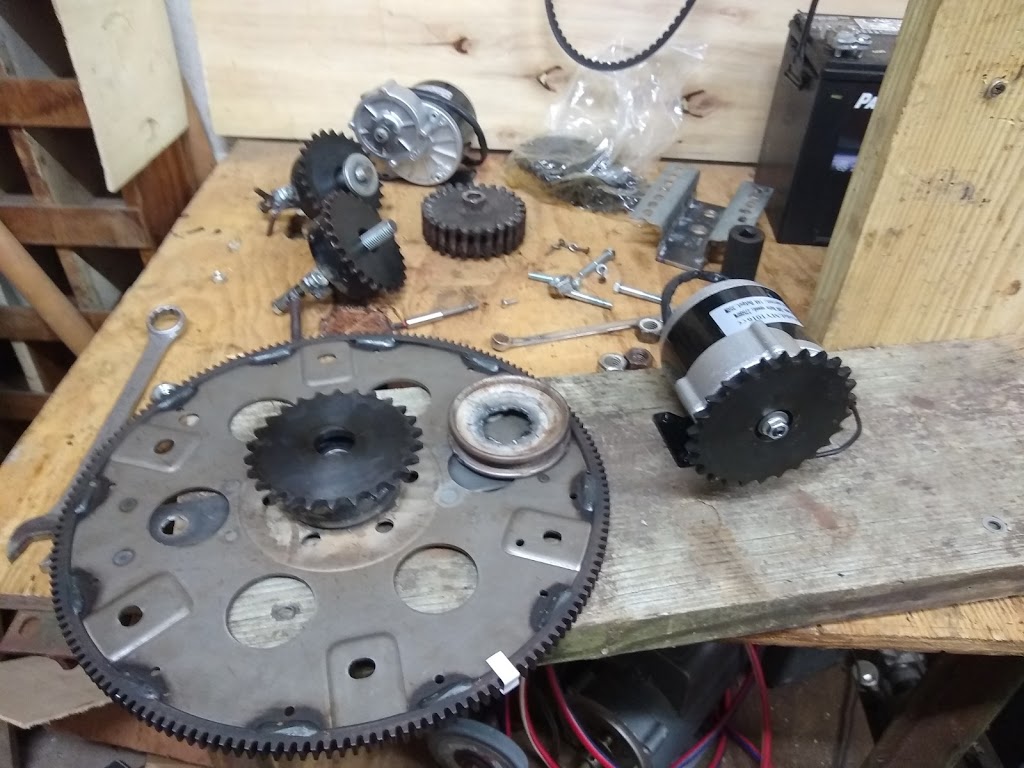
As I approach and prepare for the next set of propulsion tests for the PIE 4.7, want to note the most recent successful design changes made which do increase power output in the early bench tests performed so far. It should be noted that none of these changes require any input power increases.
***Note #2: I also have had another idea, one that seems so preposterous that I am consulting with a few trusted individuals before revealing it.***
The first three of these four are self-explanatory but we shall touch on them very quickly.
It is a definite power output increaser to:
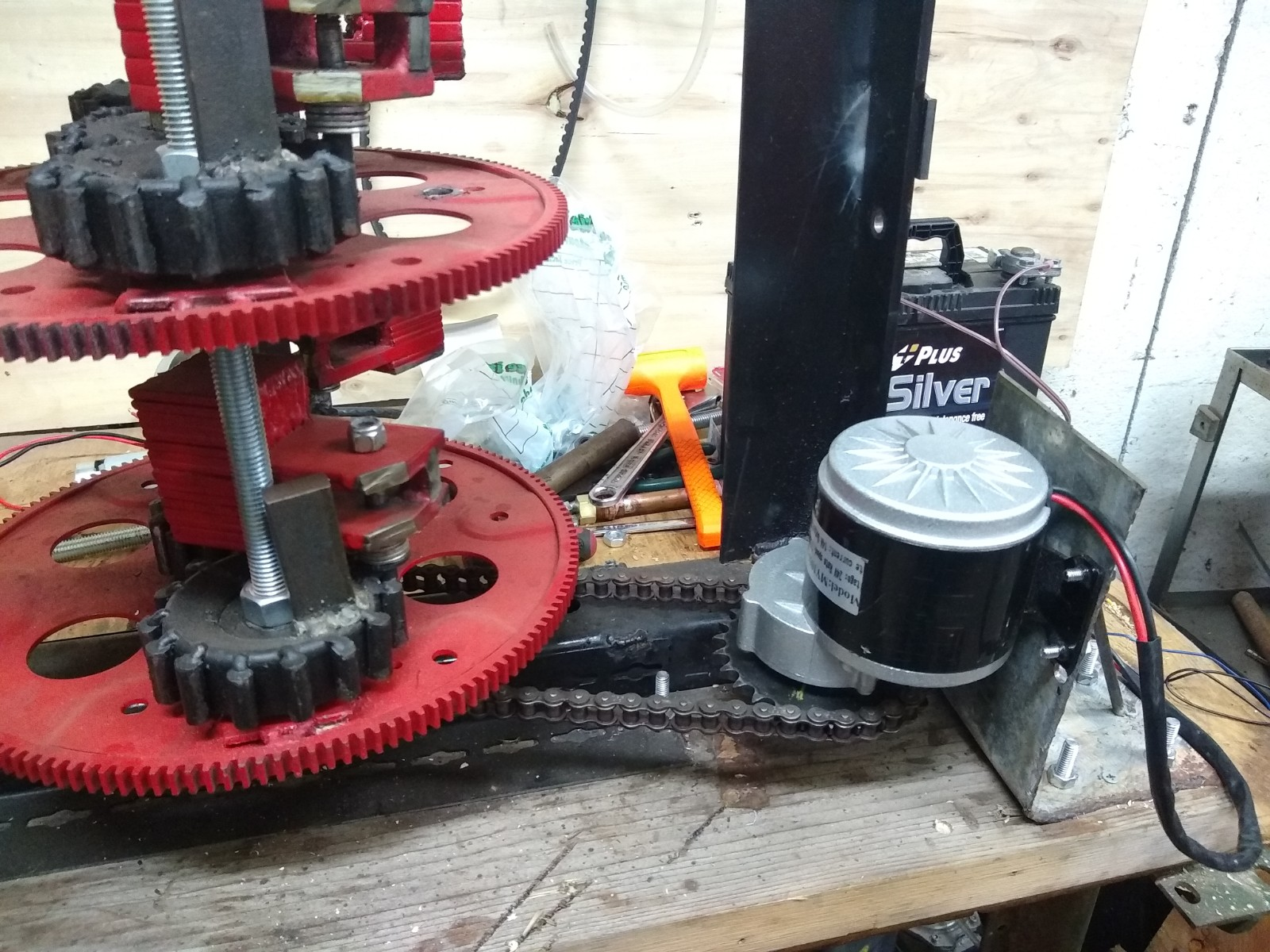
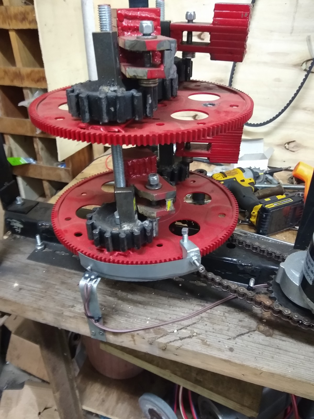
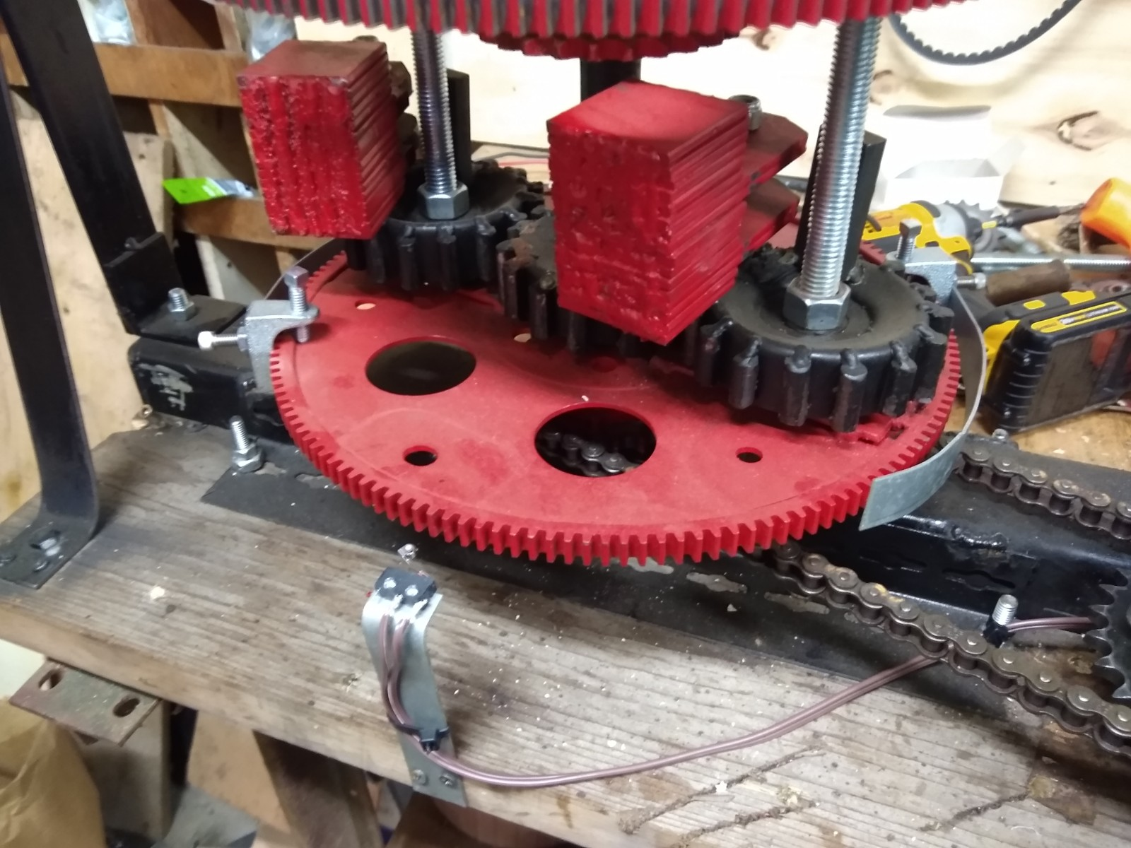
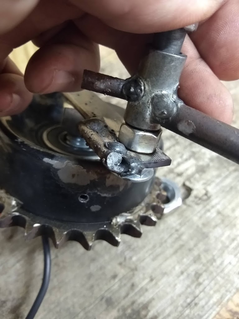
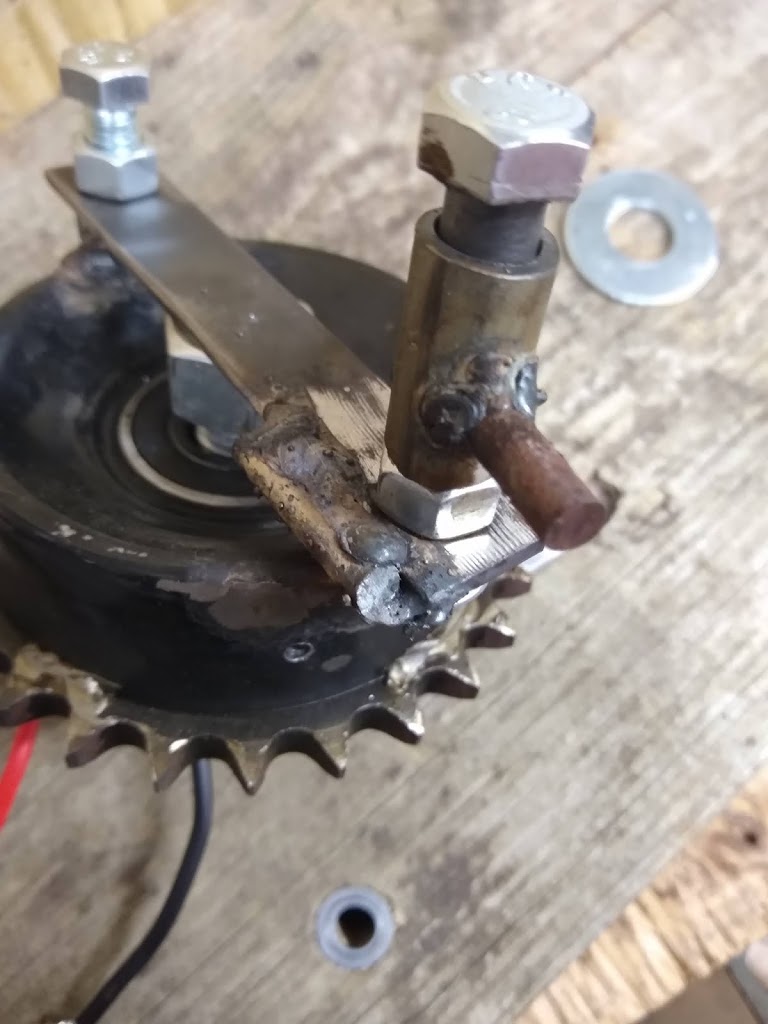
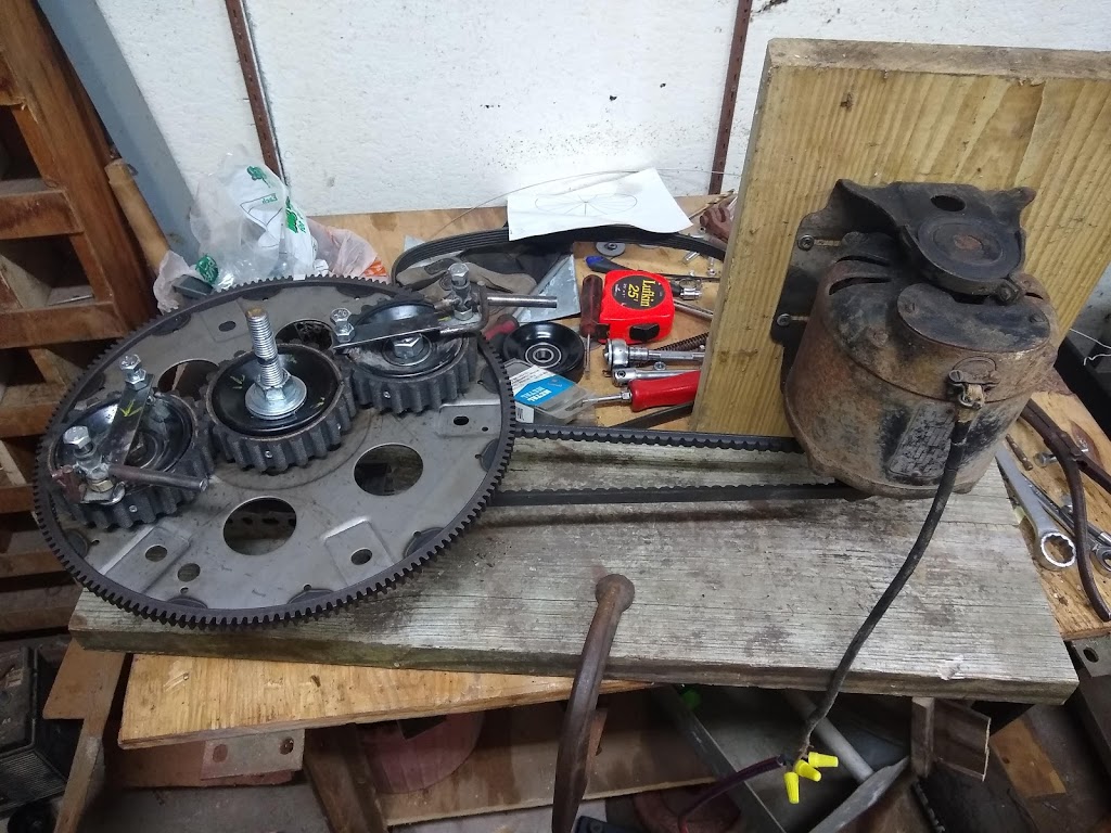
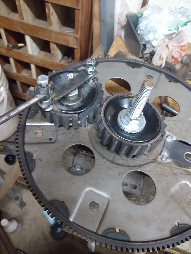
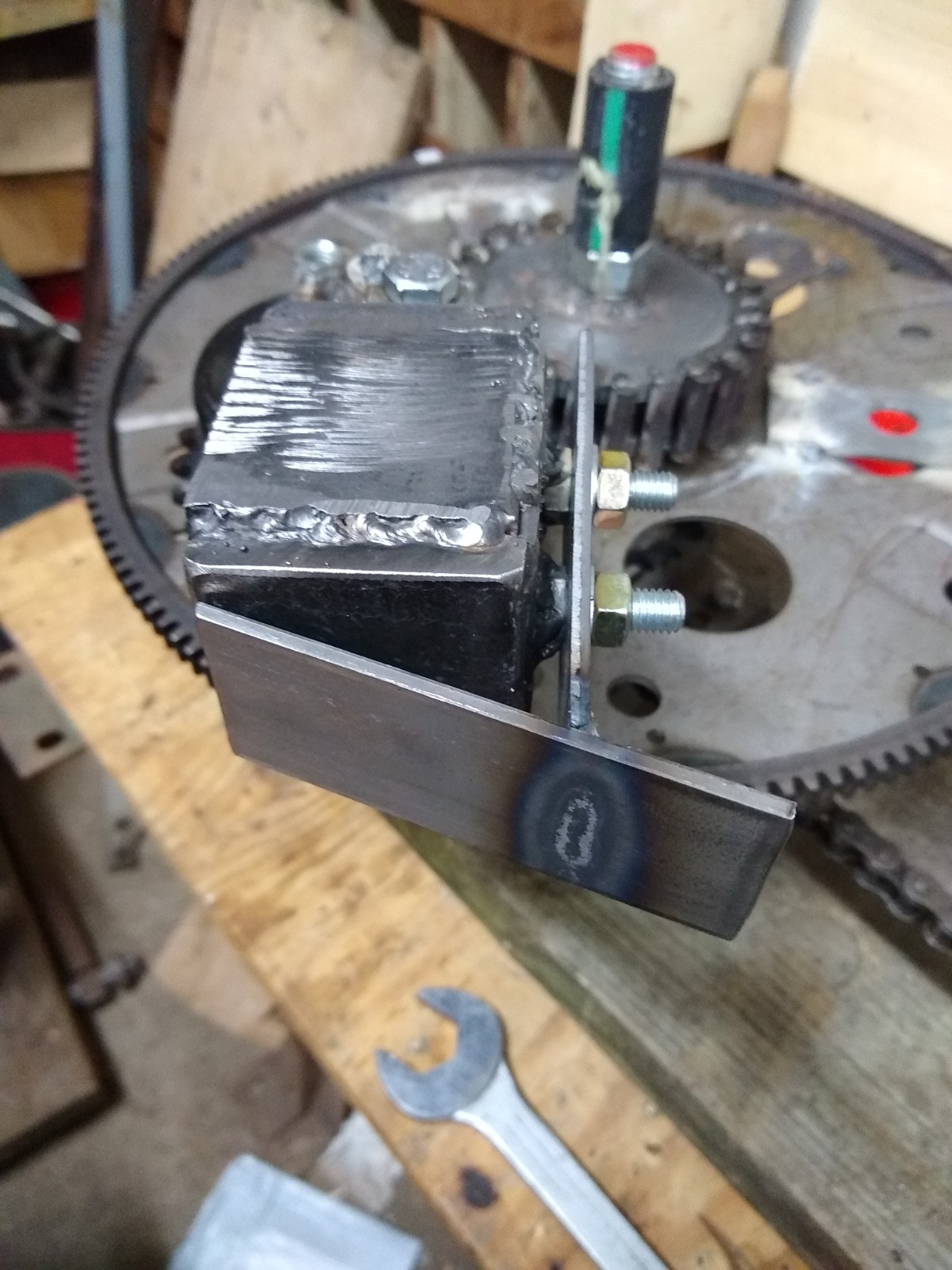
1… hold the weight in center longer (via guides).
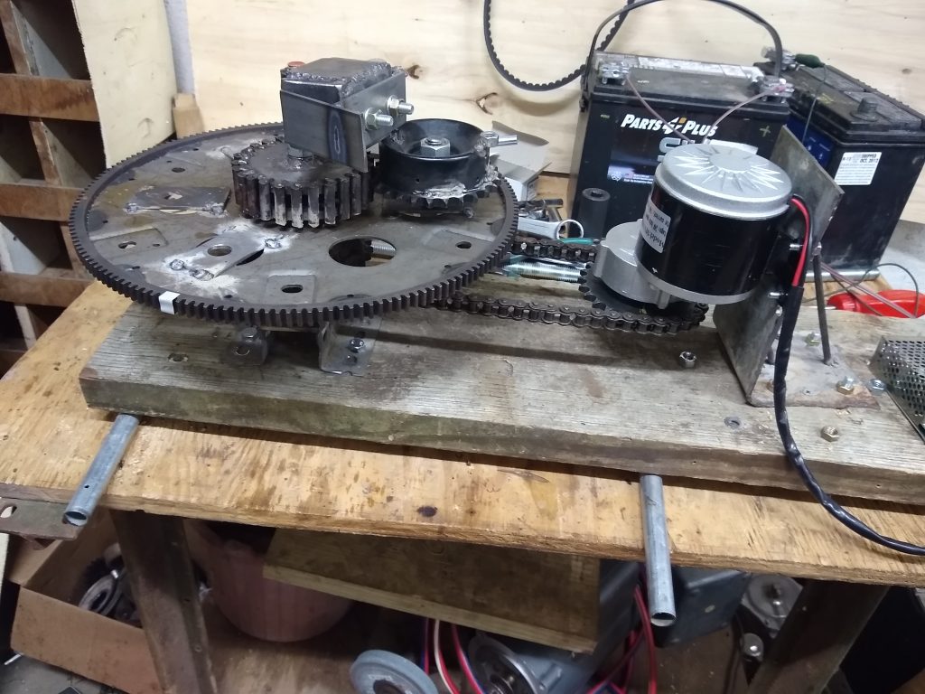
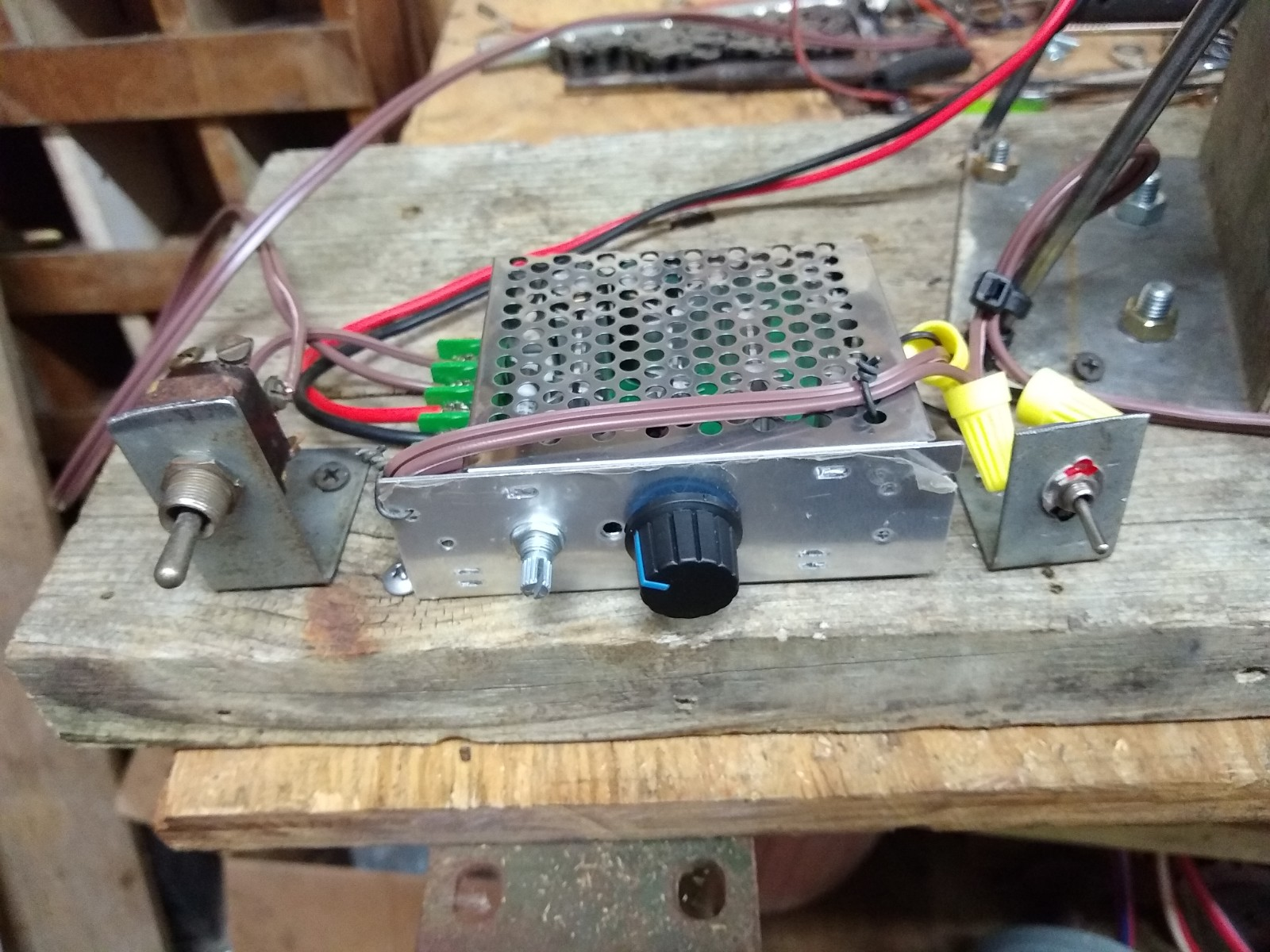
2… to be able to adjust speeds on the fly (via speed controller and SDC gain control).
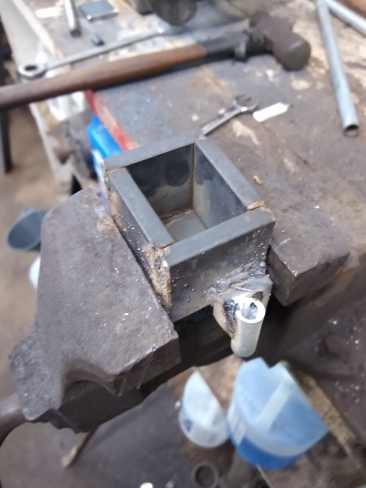
3… use dead blow weights (stronger & longer pulses without increasing input energy).
4… use the SDC (counters loading slow-down and increases pulse strength).
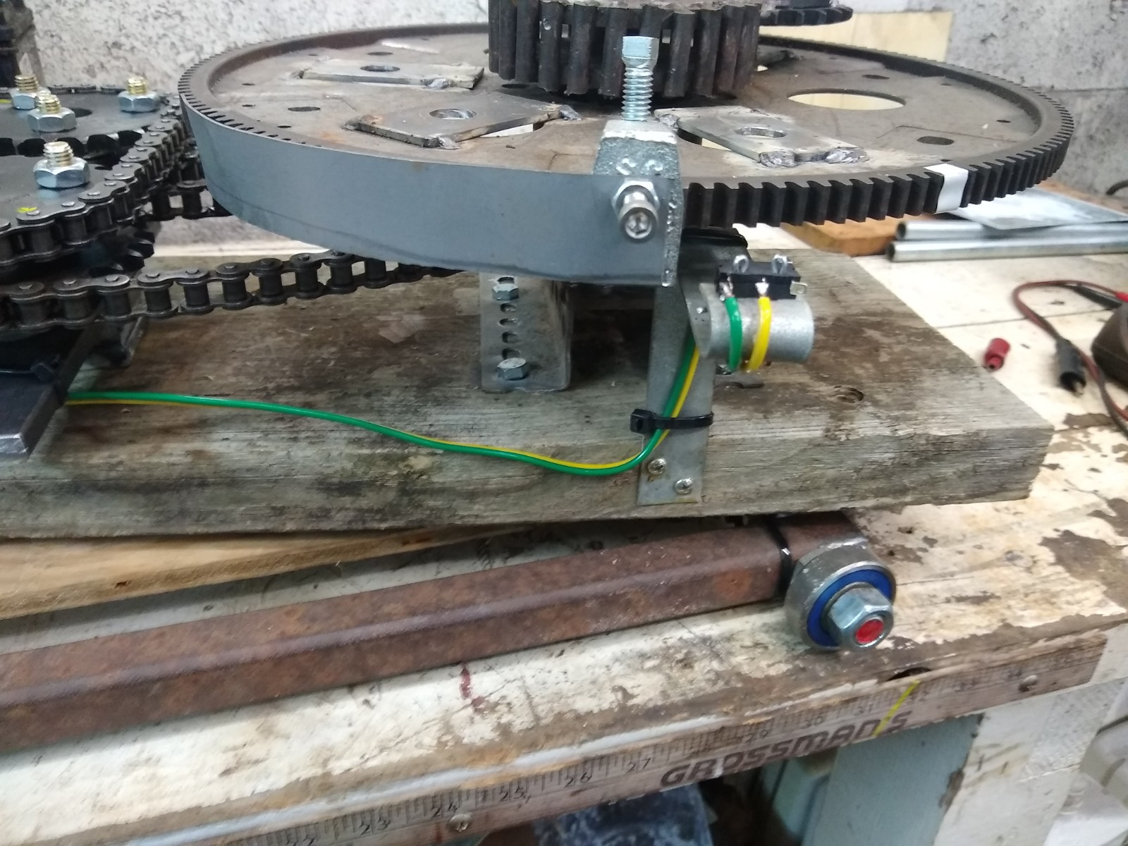
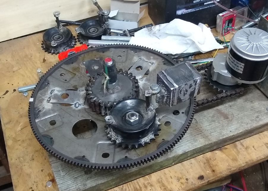
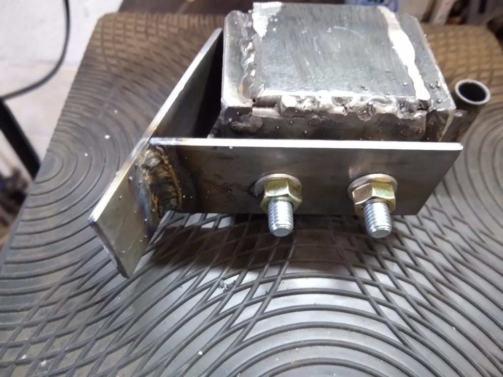
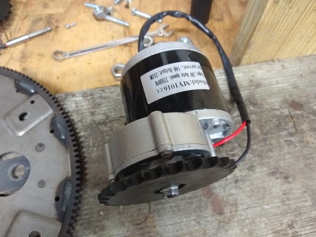
Number 4, the SDC (Speed Differential Control) is a real game-changer, so that is where the focus needs to be for now. Some of the important details & technical notations regarding this are as follows:
1st: The output goes down dramatically if speed is reduced during the “power stroke”. This was discovered when the original belt would slip at times. It stood to reason that if speed decrease was detrimental, an increase could be very beneficial. Mechanical experimentation was performed very successfully by my friend and colleague Tokio using offset (eccentric) gear drives. When he added them to a PIE design (PIE 3.* series) great power was generated, and many components were destroyed by internal forces. Electrically changing speeds is quick and efficient!
2nd: Higher speeds are known to increase power output, but reducing the weight in order to achieve the high speeds was counterproductive. The SDC can momentarily increase the speed higher than necessary to maintain base RPM, simulating a higher speed without adding damaging high loads to the mechanism or increasing input power.
3rd: Adding speed only when required adds to the outward swinging motion of the weight and reducing that speed “could” increase the impact on the outer stop to increase power.
4th: This may me a stretch of my imagination… I believe that the combination of the guide and SDC acts upon the PIE similar to the “Inner Planet Trap” did in the Roy Thornson design. I have to think that instead of speeding up the RPM at the correct moment, Roy was “slowing down” the RPM at the beginning of the power stroke and allowing the RPM to rise in mid-power stroke.
5th: Keeping the electric motor speed low is important as it reduces the overall inertial flywheel effect, allowing faster RPM changes to the PIE’s main wheel (flexplate/flywheel).
Something that can be kept in mind for future experiments would be the utilization of a CNC (think Arduino, maybe) controlled stepper motor and servo system, perhaps with hall effect sensors for feedback, which would virtually eliminate all of the guides, micro switches, gears, and chains. Even the main wheel could just be a straight arm attached to a stepper motor.
Those innovations (if ever used at all) are definitely a long way off in the future, and for now we need to learn to walk before we can learn to run.