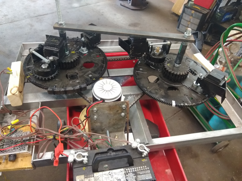
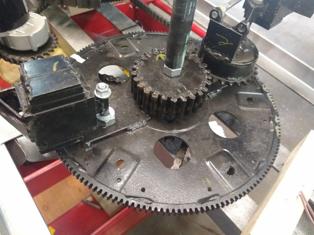
On 7/31/2021 the counter rotating PIE 4.8 was re-phased to have the planet gears synchronized (self-propulsion mode) but then one plant gear was removed from each wheel so that forward pulses will alternate from on side to the other. The non-functioning weights were fastened to the planet gear mounting holes to help balance the wheels a bit.


Results were very similar to having all the planet gears and weights in place and operational with road testing showing a 4% to 6% reduction of engine load at the standard speed of 55 MPH with little to no headwind.
I believe this poor performance may be due to the counter-rotating wheels. Previous testing has shown better thrust using co-rotational wheels (rotating in the same direction). It has been suggested that counter rotation might be needed for stability, especially in either an air or space (aerospace) vehicle, but co-rotation should be very possible with proper management using either air foils or gyroscopes. Co-rotation should still be quite manageable a with minimum amount of manipulation.
8/10/2021 Update
I have now rerouted the chain on the PIE 4.8 so now the Left and Right wheels both turn clockwise, and I have modified the ramp on one of the RH wheel’s weights for the direction change and timed the wheels for self-propulsion (synchronized). With just one weight on the right wheel and two weights on the left wheel I now see that it is a definite improvement over the counter rotating wheel setup!
The first noticeable difference between counter rotating and co-rotating is when counter rotating in this same configuration of 2 weights on left and one on the right the propulsion pulse was strong when a single weight pulsed and weak when two weights synchronously pulsed. With co-rotating wheels the propulsion pulse is strong when a single weight pulsed and doubles in strength when two weights pulse synchronously. In simple terms, the unit is stronger when co-rotational!
I need to put trolley wheels under it again to test properly on the bench, but the unit seems strong and is pulling itself (sliding forward) across the bench when running even without fine tuning the gear timing. Next, I will adjust the gear timing and modify the other weight for clockwise rotation so that I can complete this round of testing.
If there was lots of extra time to do extensive testing it would be best to build it with 4 wheels, two co-rotating and two countering them to be able to arrange them in different ways to record and study the results. I don’t feel it is necessary at this time as the testing I have done is more than adequate to demonstrate the workability of the PIE system.
I have discussed the origin of the SDC and the subsequent positive effects of its use, and when I was setting up the PIE 4.8 to co-rotate, I could visually see the point of heavier motor load in the PIE’s rotation. So I published a short video of this visually obvious effect demonstrating the position in rotation which needs the RPM boost using the Speed Differential Control (below).
More to come soon!!!