I am now actively conducting thrust tests on the PIE 4.3 with positive results.
Since it certainly appears to have a lot of propulsive force in bench tests and is rather unruly on the bench, it seems that a heavy and sturdy cart should be used.
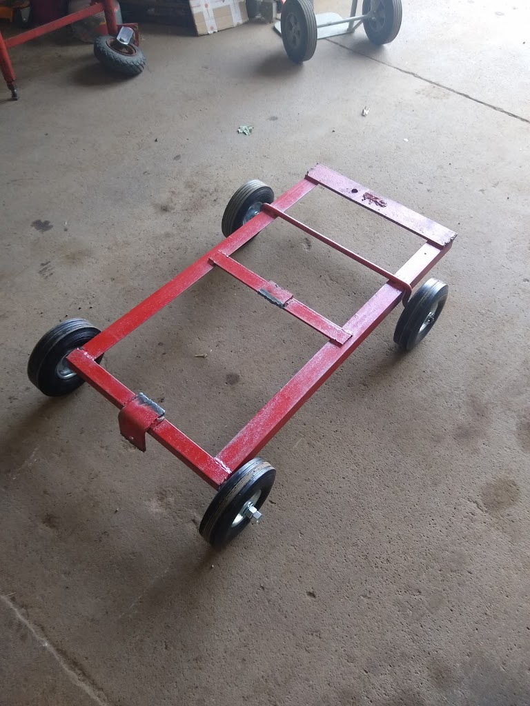
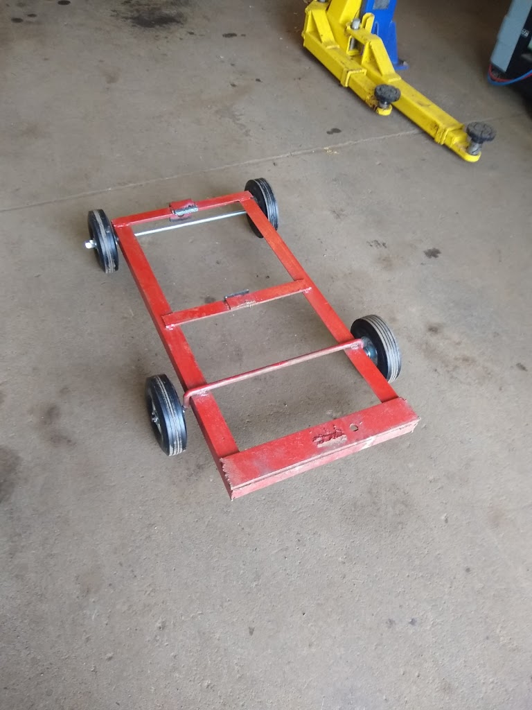
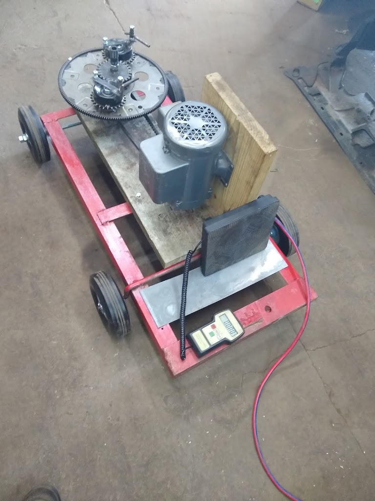
I have modified a steel cart, which I had originally built for an entirely different purpose, just to be the new PIE 4.3’s cart complete with solid solid tires and ball bearing wheels.
New Cart With New Wheels
It took several runs at nearly full speed to properly adjust the sun gear for forward thrust without pulling to one side or the other. During those test runs, there was enough force to move the cart forward and slide the wheels sideways approximately 10 inches.
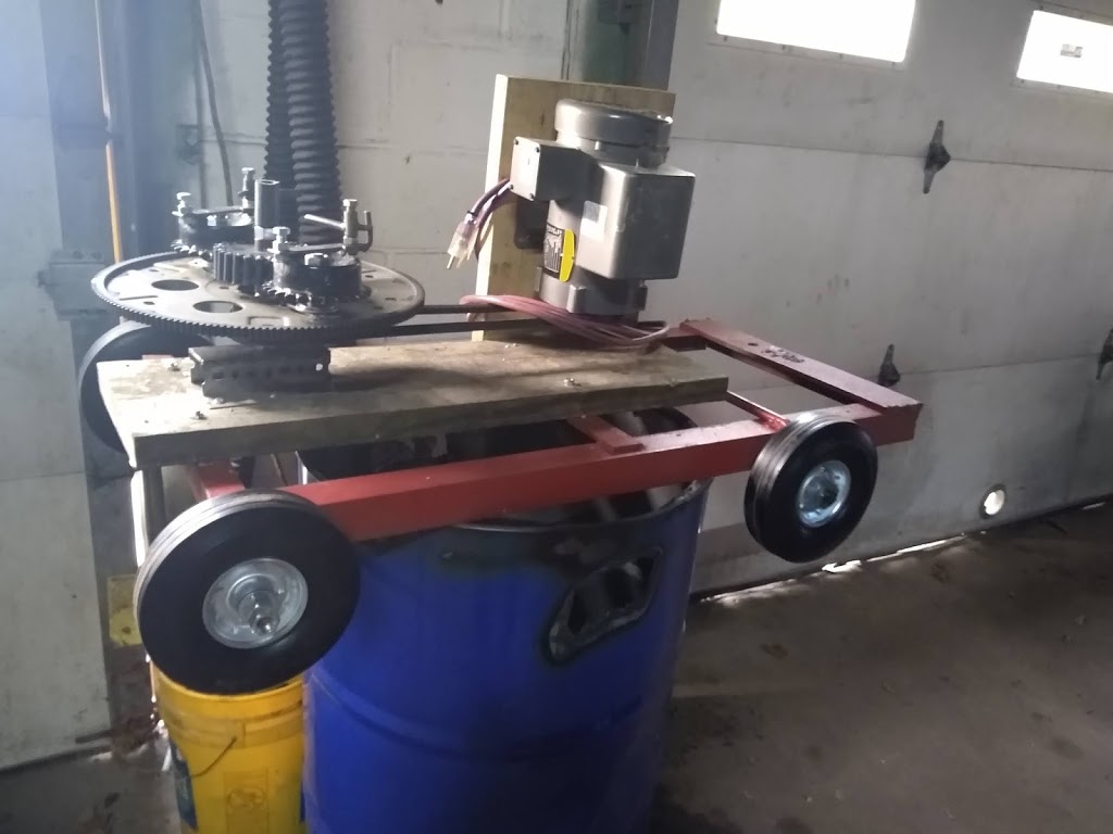
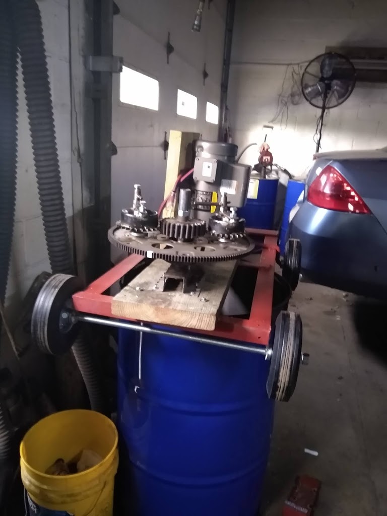
Mounting The PIE 4.3 To The New Cart
During those test runs, one outer stop broke and the excessive lash on one of the planet gears caused it to skip timing, but even though weaknesses were obvious the overall test was successful.
PIE 4.3 On Its Wheels After First Round Of Testing
The cart and PIE 4.3 total assembly weight is 130 lbs. New ball bearing wheels with solid rubber tires allow it to roll smoothly on a concrete floor, although some places on my shop floor are better than others. I have several vehicles in different states of disassembly in the shop, so I was limited to a spot where the floor is not quite as smooth so all tests have been repeated in the same “wheel tracks” to be certain that variances in the floor would not skew the numbers. All thrust and resistance tests are being measured using a digital scale.
So, on to the numbers for THIS test sequence.
Unit weight: 130 LBS.
Number of flexplate wheels: 1
Number of weights: 2
Mass of weights: 1.9 OZ.
RPM of flexplate: 275
Rolling resistance “off”: 40 OZ.
Rolling resistance “running”: 20 OZ
Result: 20 OZ of forward thrust – running at 275 RPMs.
I am really pleased with the raw power that the PIE 4.0 exhibits. This power is still quite wild and unrefined, but it is impressive, nonetheless.
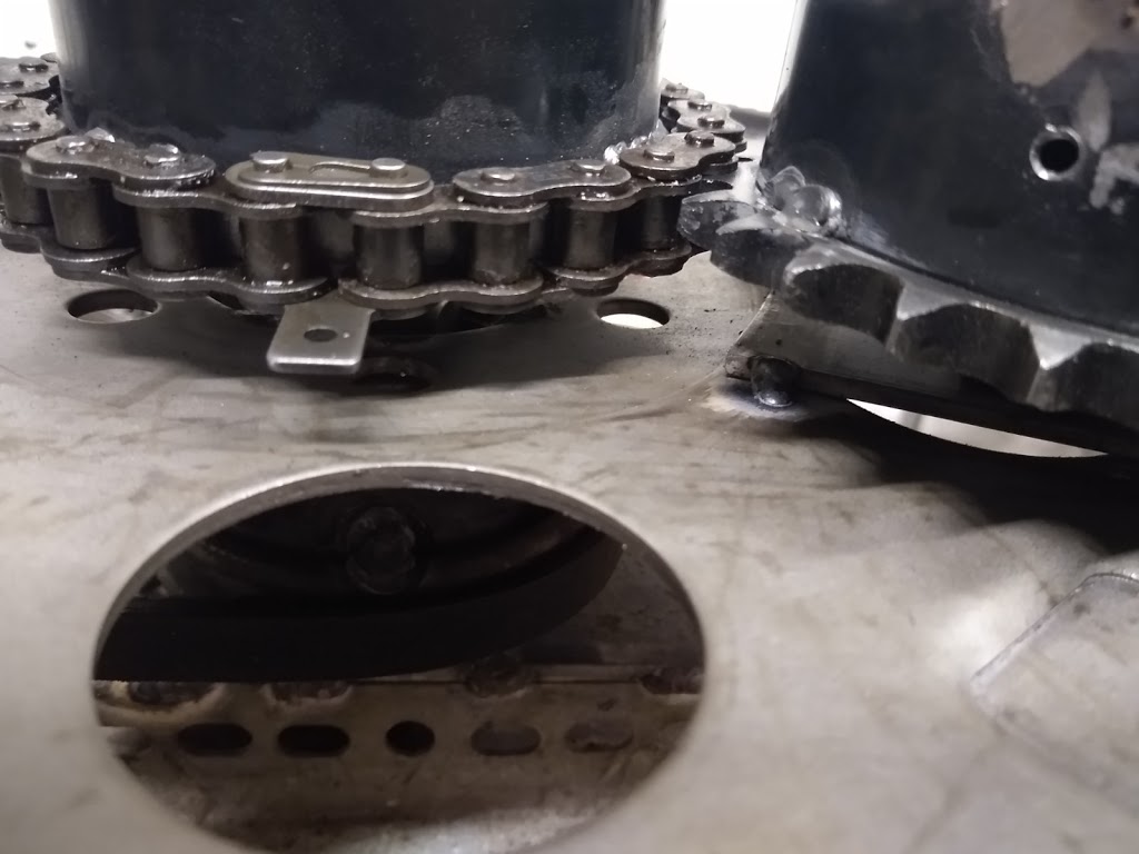
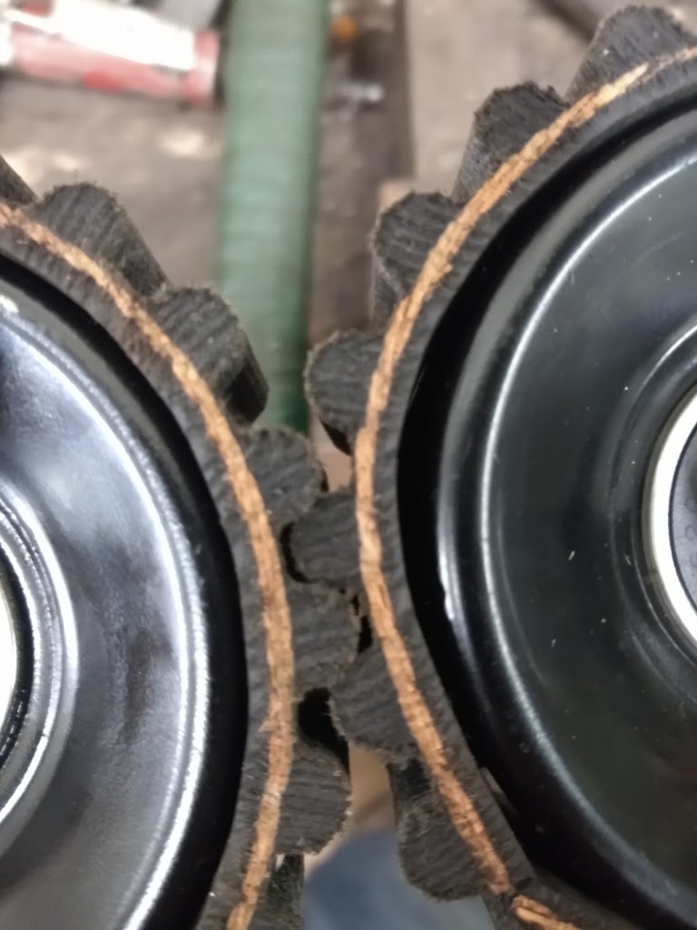
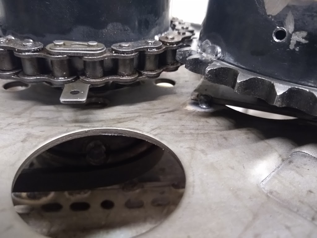
I was happy with the inverted chain design, but I quickly saw some issues that would give me trouble keeping the PIE running. Mainly the width of the chain is too narrow to allow for wheel run-out and axle deviations. The main wheel is expected to deflect some and I am not using a precision sun gear axle so I have no realistic expectation of it being perfectly straight.
Narrow Chain/Gear Mating Area
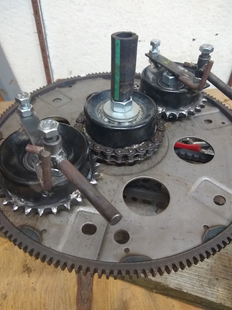
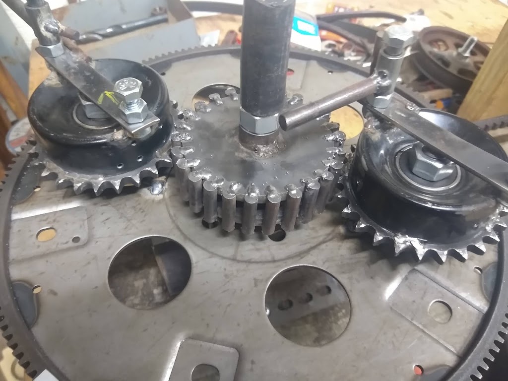
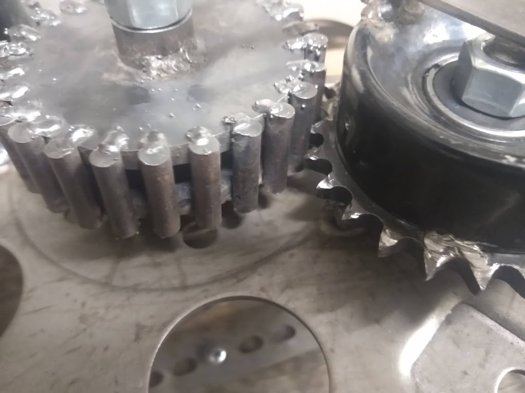
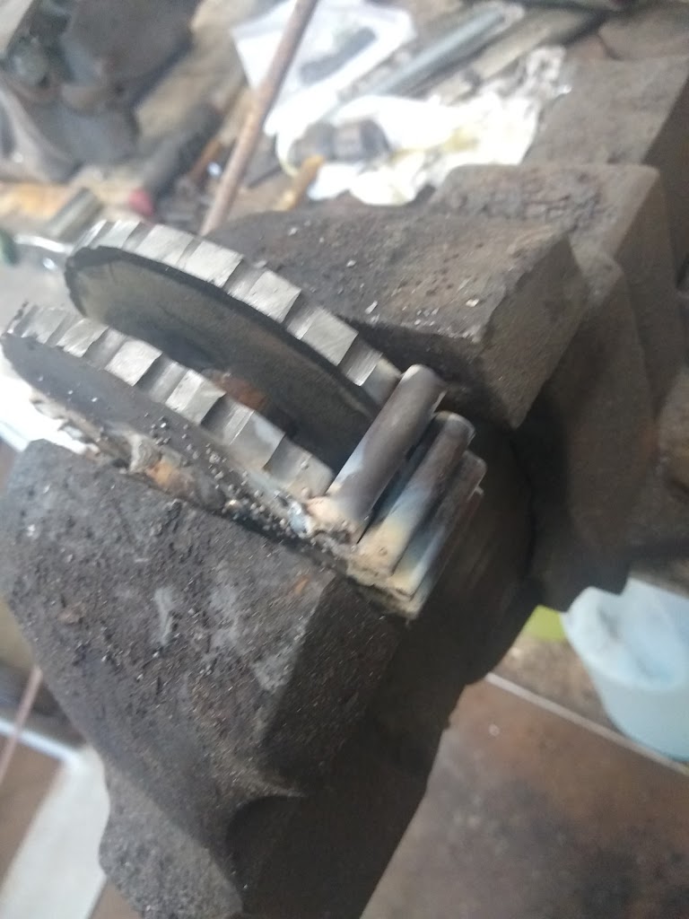
Now the sun gear has now been redesigned/improved. It still functions as an inverted chain but rather than roller chain, 8mm (5/16”) rods are used. The new sun gear width is 30mm (1-3/16”) so there is plenty of room to change designs.
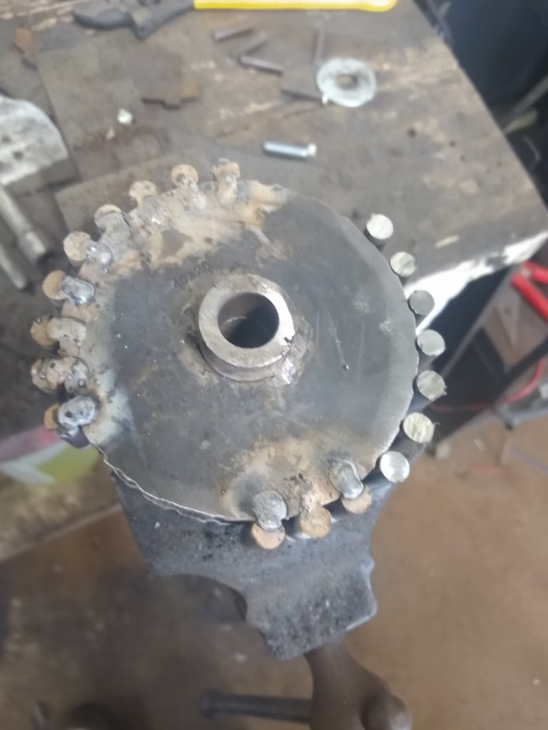
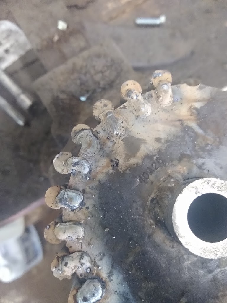
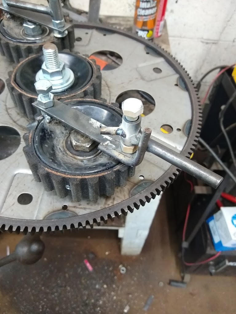
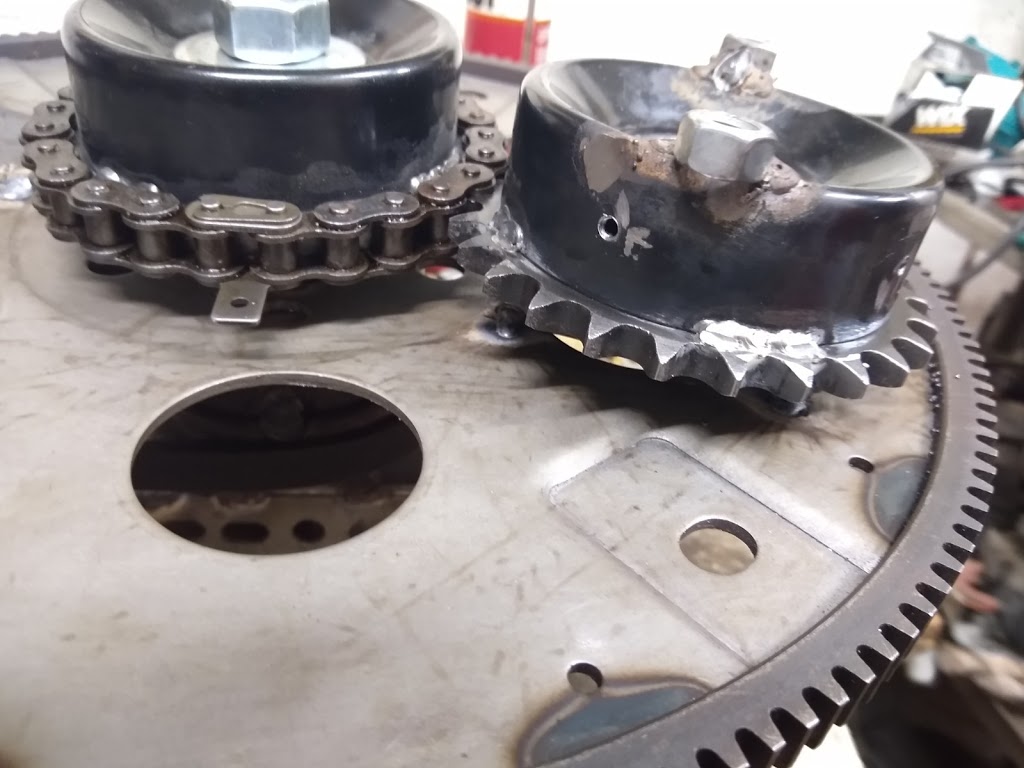
Redesigned Sun Gear
The new sun gear is made from two #40-26 tooth sprockets with the teeth cut nearly off and 8mm (5/16”) rods welded into the remaining tooth divots. A piece of 1” steel rod with the center drilled to 5/8” is used for the center of the gear. The sprockets are welded to the center rod and the 5/16” rods ae then welded in place.
Bench testing is showing that adjusting the sun gear’s timing by as little as 1 or 2 teeth (13 to 23 degrees) changes the direction of thrust dramatically.
Below is a video of the new sun gear set for forward motion and PIE clamped firmly to the bench.
I am planning on doing more extensive testing in the next days and weeks, including the use of an inverter to make the drive portable for vehicle testing!
It has occurred to me that since the PIE 4.0 has already gone through 2 gear redesigns and a motor swap that this is truly the PIE 4.3, so that is what it shall be known as… PIE 4.3!
As we open a new chapter in the PIE project previous chapters are not closed, instead they continue as the earliest pioneering efforts put forth leading to PIETECH and will undergo more extensive power in/out ratio testing for scientific purposes.
The PIE 1.0 & 2.0 are also the necessary “trainers” to teach the concepts of PIETECH, and actual building plans are forthcoming within the next few months!
Update added: The PIE 2.0 requires just over 30 oz of thrust to self-propel as seen in the earlier posted video. Another test was run, using weights placed in front of the PIE 2.0. The weights were added until it would not move them, then backed off until movement was just apparent. Then a digital scale was used to push the whole rig forward in order to determine maximum thrust (stall method). This test was repeated a total of 8 times with identical results.
Maximum thrust is now calculated at 230 oz which is 14.375 lbs or 6.52 kg.
Bryan-
PIE 3.0 is a hybrid design which has been which has some unique features which include an active RPM control system using offset pivots. The PIE 3.0 has thus far shown itself to have tremendous power potential but the early tests have proven internal stresses which are very difficult to contain. This 3.0 design is a collaborative effort being developed in a separate lab.
PIE 4.0 is a high-speed PIE designed to run well above the speeds of the PIE 1.0 & 2.0 and designed to explore the power of speed v. weight. Early designs have focused on increasing the mass of the weights, and has proven that increasing the mass is effective to a point but that increasing the speed has a much greater effect with very small incremental changes.
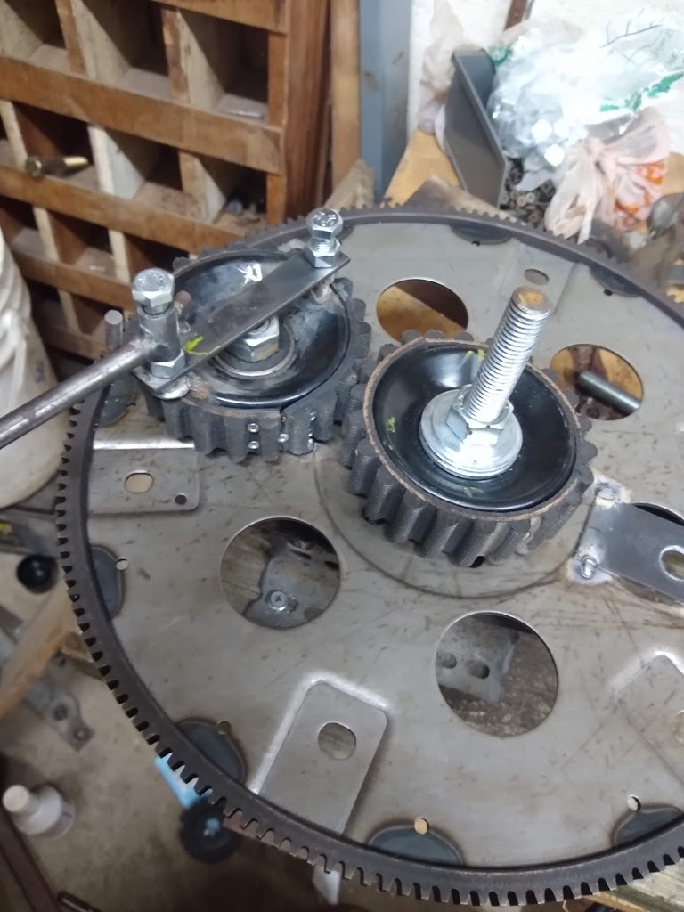
High-Speed Planetary Gears
The fist obstacle to a high-speed drive is the planetary gear set. While high speed spur gears are available commercially, the cost for these gears tends to be prohibitive for experimental use in which component damage is rather common.
The Planetary gears need to be able to smoothly run at speeds exceeding 1000 RPMs as well as run within reasonably acceptable noise levels.
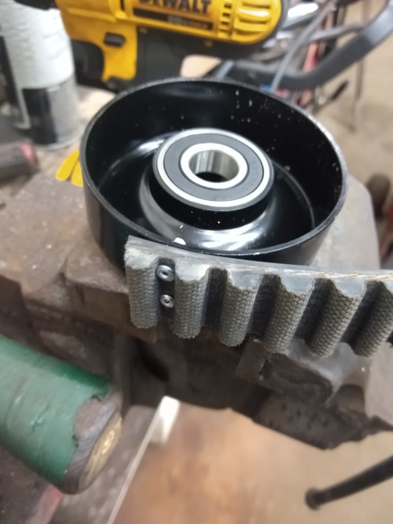
1st Experimental Gear Set
The first experimental high-speed gears have been made with reinforced cloth covered flexible material from 14mm pitch industrial timing belts, and although this is very quiet, they flex too much and timing between gears is impossible to hold. This may be revisited another time but is not considered viable for experimental use right now.
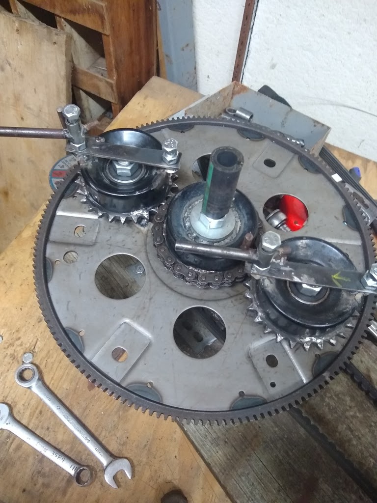
2nd Experimental Gear Set
It has been decided (for now) to use chain sprockets for the planet gears and an inverted chain drive sun gear. The inverted chain drive is simply a sprocket with the teeth cut down about 90% of the way. A roller chain is wrapped onto the gear and the divots formed at the bottom of the teeth hold the chain so it cannot slip. The chain ends are connected with a standard connector and has not had any need for further work or welding so far.
The only problem experienced with this has been that of run-out due to the sun gear axle getting bent slightly and the deflection of the flexplate. The (possible) solution to those issues has been worked out and will be reported here when it is unveiled.
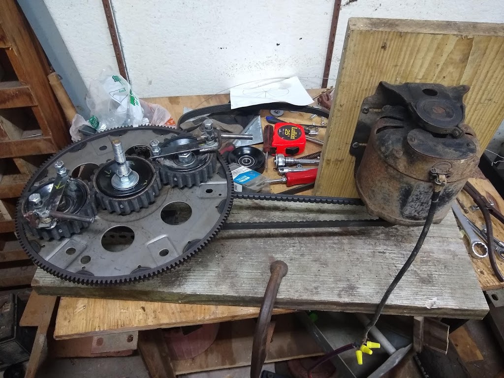
The PIE 4.0
The new PIE 4.0 has now been bench run. It uses very low mass (1.94oz) weights and a 110 volt motor to spin it. The RPM tested at this point is 850 (+/- 10 RPMs).
The high RPM certainly does make a difference, as the PIE proceeded to dump the bench and its contents the 1st time and then with the 2nd run (which was videoed) it pulled itself out of the c-clamp holding it to the bench. That is a lot more power than was anticipated.
The latest incarnation of the PIE is kind of a step back to an earlier design as well as a step forward to push the limits of PIETECH possibilities.
I am using a single wheel (for now) with a much lighter weight, even lighter than the PIE 1.0 design. I am trying out a quiet gear set which uses a 14mm pitch timing belt as the teeth which is fastened to the same size (3.5″) steel pulley as used on the PIE 1.0 & 2.0, and although it is quieter I am not sure if the teeth are robust enough to use as a spur gear.
Initial testing of the PIE 4.0 is very encouraging, although there are some small issues arising from the increased speed which has currently been measured at just over 750 RPMs. The most serious issue has been the used motor I pulled off of the storage shelf. Although the 110 volt motor was marked as “Good” because it runs well without a load, it quickly overheats and shuts down when it is turning the PIE4.0. The other issue is the soft gear design which seems to work well most of the time, but has “slipped” out of time on several test runs. I may revert to the welded steel gears before I am done since I still do not feel that purchasing expensive spur gears in this size range, just to risk having them destroyed if the design fails elsewhere, is an acceptable risk. Eventually I am sure that it will become necessary in order to achieve high speeds for extended periods of time.
The lighter weights (2 oz. including the pivot bushing) are actually performing better than expected as thrust becomes readily apparent in the 100 to 200 RPM range, although a better study of this is required.
The PIE 4.0 has only been bench tested so far, but it easily moves my bench around when it is clamped to the surface of it. Since the PIE 2.0 was just barely able to move the bench, I am encouraged to keep pushing forward with this high speed unit.