First:
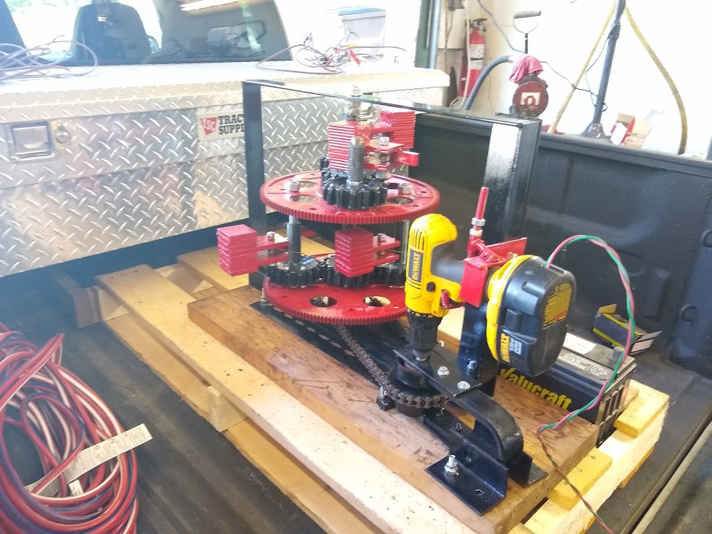
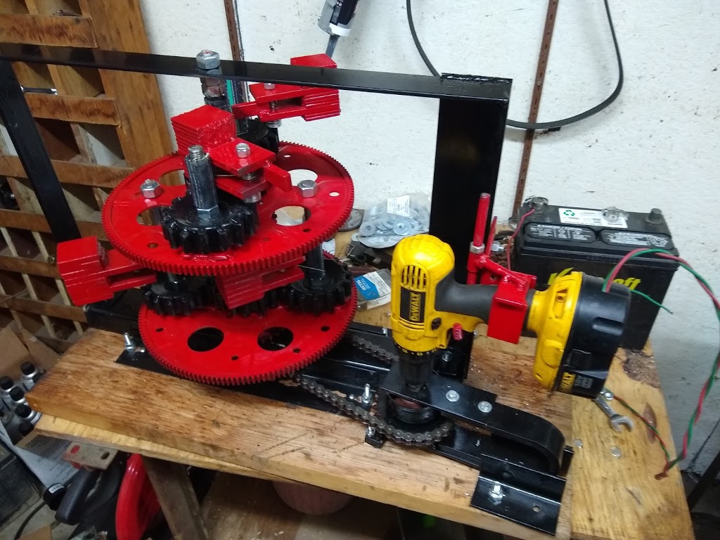
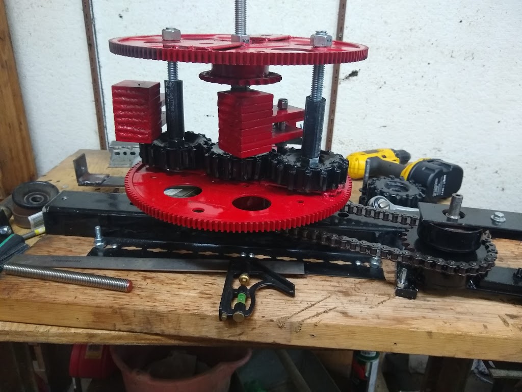
The PIE 2.0 project has commenced. As could be seen in the pictures contained in my last post, a new weight is being developed for PIE 2.0. I plan on using the same design for the planetary gear sets because I they are simple and robust. I was not sure about the flexplates, but since they are already prepared for the purpose, I will use them until a reason to change presents itself. Some parts are being reused (from the 4-wheel unit) and/or repurposed. There are still many questions to be answered and most of them need to be put on the work bench in order to find the answer.
We know that computer models and all the advanced trigonometric formulas in the world are useless unless there is a way to put them to work. The differences between types of drives can be discussed, compared & argued but the proof is in the workshop. Sooooooo… I need to make something PERFECTLY clear.
The fact is, this damn thing works!
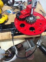 |
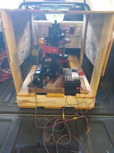
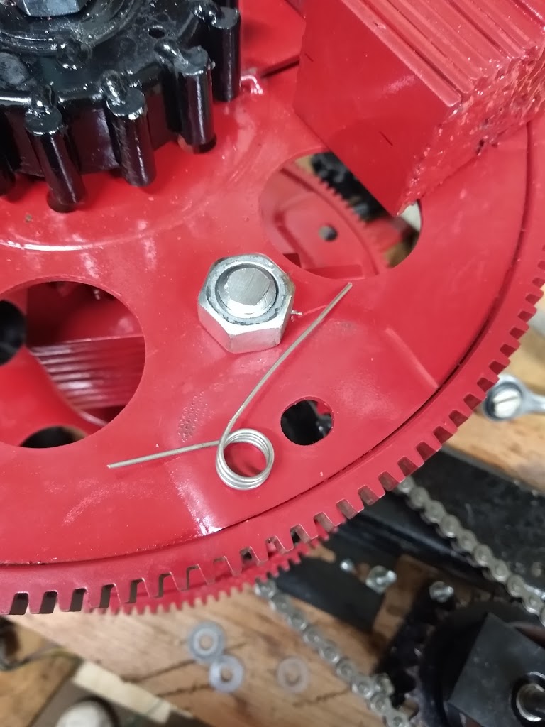
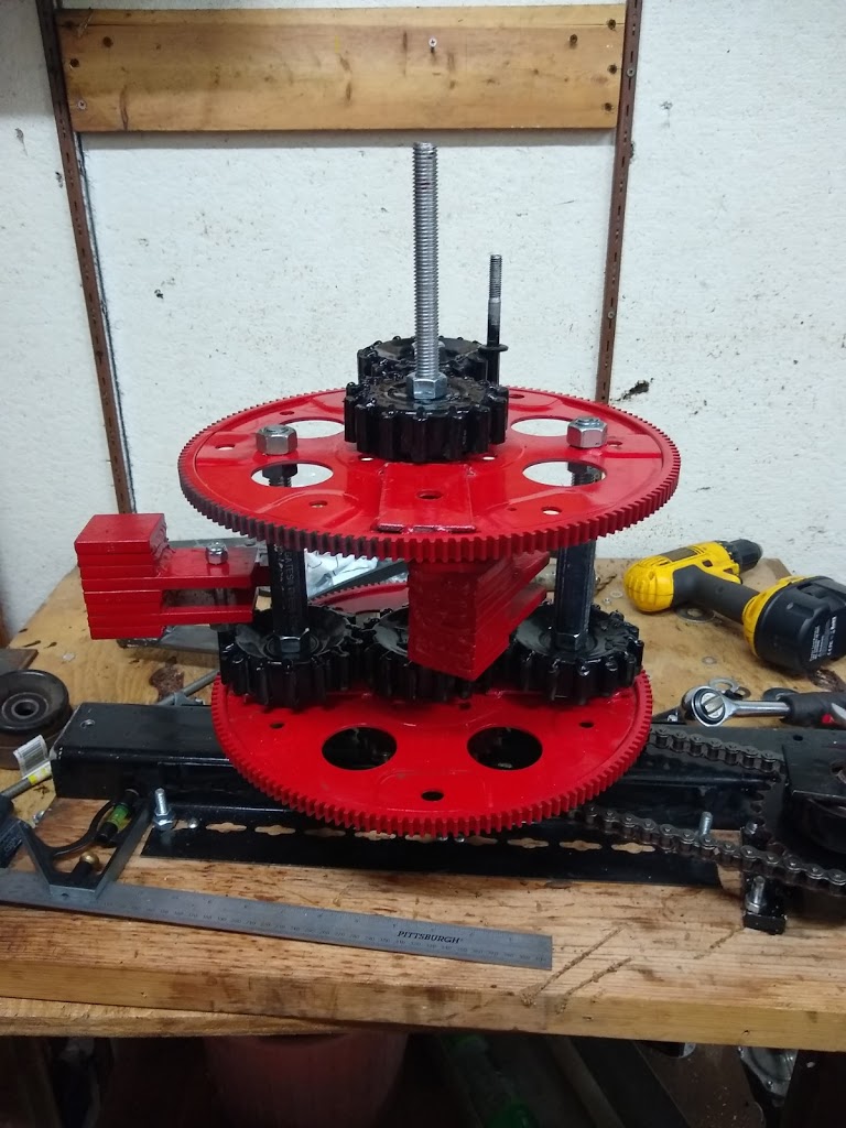
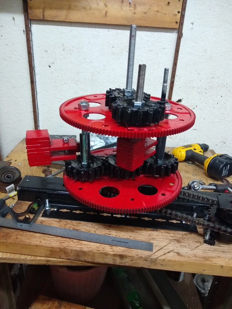
| Setting up for bench Testing |
 |
| Setting up for bench Testing |
Second:
The Problem with Physics is that Some Science is Not Allowed:
Science is: The observation, identification, description, experimental investigation, and theoretical explanation of phenomena.
Physics is: The science of matter and energy and of interactions between the two.
Our currently taught physics does not allow for certain outcomes, and any drive system that does not push against anything for propulsion is one of those outcomes not being allowed for.
Along with physics departments worldwide, NASA currently discounts this type of tech as fantasy. Yet NASA is currently using reactionless propulsion to position/reposition satellites in Earth’s orbit.
Countless scientists have witnessed a very early version of this system operate with greater efficiency than wheel driven, jet, propeller, or rocket driven forms of propulsion, yet they turn right around and state unequivocally that it is impossible and absolutely cannot work…Ever!
Many witnesses will deny that they ever saw, or that there ever was, a working demo.
People’s lives have been ruined because they built a working device and tried to sell it to big business and/or governments.
Science teachers worldwide are told that if they teach this as a possibility, they will be fired. The only way this can be included in a curriculum is by “proving” it doesn’t work.
It seems that the ONLY ALLOWABLE outcome has been negative or no.
Since this Grassroots project flies in the face of all of that, I continue to publish ALL information regarding the PIE system (1.0, 2.0 and future versions) and as stated earlier, the inconvenient fact is that this damn thing works!
I hesitate to say that I am working to change the paradigm, but it works and it is repeatable.
This knowledge NEEDS to go public, needs to be peer reviewed, and needs to be put to use helping people everywhere travel more efficiently.
Third:
PIE 2.0 To-Do List (Subject to Change of Course):
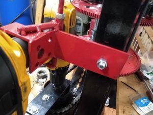
1- Set up outer stops for the new pendulum weights
2- Enhance bearings on all rotating assemblies (Doubles?)
3- Strengthen framework to withstand higher power output
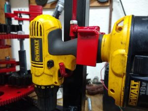
4- Higher speed & strength motor
5- Synchronous drive system (Roller chain, T-belt?)
6- Consider “stacking” flexplates rather than side-by-side positioning to reduce footprint
7- Consider sourcing off-the-shelf parts for future versions, kits, etc.
Fourth:
A personal note:
As I am writing this, I want to thank everyone for watching my videos and reading my words.
I need to remind everyone following along that I am funding this completely out of my own pocket and then sharing it freely. I am not accepting donations nor am I selling anything for funding or profit.
There may be a saleable product in the future, however, ALL of the info in my personal journal & subsequent public blog are still going to be free as long as I have a say.
Perhaps, eventually, kits might be made available. I can imagine a kit to add hybrid capability to a vehicle for about the price of a go-kart.
Right now, I want to share this with everyone, worldwide. I would hope others would see how simple this is to build a PIE as well.