Page 26, TEST DATA!!! Coming Up Next, PIE 2.0

Test data is coming in now. After a few hiccups in the testing procedures, the data is clearly indicating that the PIE is taking a small percentage of load off the test vehicle’s engine.

 All percentage of engine load reduction readings are automatically averaged by the scan tool taking those readings.

All readings used in this test phase taken by Matco Interrogator, which is the Matco branded OTC Pegisys scan tool.

1-mile test track with 20mph speed limit and 2 stop signs: 2% engine load reduction.

Same 1-mile track with battery at 10.5 volts: 2% engine load reduction.

50/50 highway & city (light traffic) 55mph & 30mph limits respectfully: 3 % to 5% engine load reduction. Traffic variations causing engine load reduction variation

These conditions were repeated over and over with solid repeating results. So it is official, PIE 1.0 is a success, testing reveals that it works as an add on hybrid system. I think that the most amazing revelation is that the PIE exerts enough force to be recorded using a car windshield wiper motor as its prime mover.

Testing will continue as I work toward a PIE version 2.0. This next version will be much more powerful.

A new PIE 2.0 To-Do list will be published very soon.

Stay tuned, the exiting stuff has yet to happen!!!!

Page 25, Project Goal Added, To-Do List Updated

I have a very important goal added to the design phase of PIE 2.0. It is something that crossed my mind in the beginning but was not something that was as important as simply getting the drive to work. Now it seems more important than ever to stay with the true spirit of a “Grassroots Mechanic Movement”!

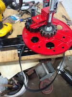
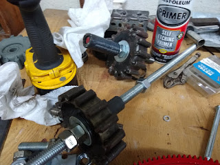
Simply put, the PIE needs to be an engine that can be built by mechanics everywhere with average shop tools & equipment with a minimum budget. No needing a lathe, milling machine, shaper, dividing head, or other tools which are common in machine shops but not in the average mechanic’s workshop or garage.

I do have most of these available to me but as I was getting ready to buy material and set up machinery to make parts, I asked myself “how many mechanics have this option available to them?”, and the answer was “damn few, that’s how many”.

The common hand tools along with a welder, grinder, and chop saw are all the equipment required so far and it is my goal to keep it as simple and inexpensive as possible. It would be great to use machine shop equipment and expensive off-the-shelf components, but I think that these things are unnecessary to build a working unit (PIE, Thorson Drive, or any other)!

The updated “To Do” list (for PIE 1.0):

1- A better locking mechanism for the sun gears to the axles.

2- A way to vary the sun gear timing by adjusting axle position.

3- A different drive system from the motor to the plates, maybe a double-sided timing belt or a roller chain drive.

4- Explore the possibility of having sun & planet gears on both sides of the plates.

5- Mount in a motor vehicle for road testing.

6- Collect “Empirical” data from real world testing

7- Make sure PIE can be built/fabricated without the absolute need for machine shop tooling

8- Keep material total for one completed PIE under $200

9- Complete testing of PIE 1.0 & start building PIE 2.0  

10- Start To-Do list for PIE 2.0

Page 24, On-Road Testing Now Underway

I am performing the on-road testing phase now. I will say that I am impressed so far, even without completing a recorded data set. It is truly amazing to feel the vehicle being pushed along using so very little power, while also decreasing the amount of throttle given to the engine because of the engine load decrease.

The only change I have made to the PIE is the addition of a switch and relay to control the PIE from the driver’s seat.

In the shop, I am preparing for PIE 2.0. I deliberated heavily about the planetary gear sets. I would like to replace them with machined gears which would run quieter and smoother, but I will stay with the simple fabricated gears for now. I already have parts made to fit the fabricated gears, so this will save the time and the expense of rebuilding some components.

I seriously thought of upgrading everything, bearings, plates, gears, weights, etc. but cannot justify that at the present so it will have to wait for version 3.0 or higher.  I am, however, planning on running weights on both sides of the flexplates. This should allow for heavier weights and higher RPMs which will both equal more thrust! 

Intro:

Welcome to the Grassroots Mechanic Movement Blog: 
Most of the contents here are my personal notes & pictures, placed here as a record of my journey. It is not a written for anyone in particular. 
Comments are encouraged, even if only to say that you were here.
Thoughts, notes, or suggestions are welcome. 

Some visitors will undoubtedly wish to tell me how foolish and impossible this is, please do not bother, as flaming and/or non-constructive criticism will not be well received here.
I am B.
I am a professional Auto Tech with more than 35 years in the automotive mechanical industry. I am currently a garage manager responsible for the maintenance & repair of more than 20 vehicles in the Northeastern U.S. “Rust Belt” and I am looking forward to retirement.
I can be a grumpy old fart with little patience for closed-mindedness, so no apologies are offered if I offend anyone by being myself.
I am also an ASE certified Master Auto Technician, hold a Bachelor’s Degree in Automotive & Transportation Technologies and have earned many automotive, truck, bus & business certifications.
In short, I know how things work.
I am making this blog to make public the development & usage of this truly revolutionary technology that is capable of making almost any vehicle into an electric hybrid.
I am only one of many people building & testing this, and similar, tech worldwide. There are multiple designs which have been proven to work and this is only going to really discuss the one “originated” by Brandson Roy Thornson, and reworked by me personally.
This is a Closed-Loop Reactionless Impulse Propulsion system, and, yes it does actually work.
I expect:
Plenty of scoffing.
Accusations of making fraudulent claims.
Backlash from people who would rather not see this tech go mainstream.
Again, I am a grumpy old fart, so if anyone takes issue with my work it really doesn’t matter.
There are many well informed, educated, brilliant individuals who state unequivocally that his technology is nothing more than a pipe dream and/or pure bunk.
If you want to “blast” this content, I respectfully ask that you keep an open mind, be civil, and email me privately. I have neither the time or the patience to discuss this with anyone who just wishes to cause disruptions.
This is not a new technology, and although it has been demonstrated many times, there are those who close off their minds and refuse to entertain ideas which do not always fit into nice neat little packages.
Along with other fellow technicians, engineers and mechanics scattered around the globe, I am going ahead with revealing this tech at my own expense as a fully Open Source Project.
I have been writing this blog privately since the inception of this project and I think it is about time that I make it public.
I will be editing and then copying/pasting my original documentation here.
More will come as time allows.
Thanks for visiting & I truly encourage everyone to experiment with this tech.
——————————————————————————————————–
A Note to all open-minded Mechanics & Experimenters,
(Added 4/10/2020)
 
This informal document’s purpose is providing information regarding a privately funded & produced project to build & test the feasibility of a reactionless propulsion system to be used in the transportation industry as a hybrid drive system that can be added to existing vehicles of multiple types. The electrically driven propulsion system I am outlining here is based on the Thornson EZKL Drive invented and partially developed by Brandson Roy Thornson. This and similar Thornson-like drives have been functionally proven, independently tested, and I can personally attest that there is no trickery involved.
While there are other types of potentially effective designs, this is intended to outline this functional Thornson-like Pulsed Linear Motion Generator and promote the dissemination of this information by promoting a Grassroots Mechanic Movement. This Technology needs to be developed and used without being restricted by any entity or entities who would see this monopolized or suppressed.
It has been vehemently opposed by the mainstream scientific community who are not willing to review and reinterpret the widely held concepts of movement conservation even when demonstrated via working machinery.
People who have invented, promoted or attempted to market similar tech have been stopped. Some were discredited through manipulation of public information, others were blacklisted – even after their device(s) were reproduced and tested by mainstream institutions (SUNY Buffalo, etc.).
This is the reasoning regarding the need to get this information to experimenters, and hobbyists through a grassroots type movement.
This tech is very reproducible at a reasonably low cost. It was built utilizing many recycled & re-purposed components. It is also very understandable to the mechanically inclined without any specialized training or the need for any advanced mathematics.
Review this data & please reproduce this tech for yourself.
Build it, use it, and show others how to build it.
That is the core of the Grassroots Mechanic Movement!
 
Truly,
B.
P.S. PLEASE ALSO NOTE: The construction techniques & methods along with the parts & materials used are not intended to comprise a finished device but are only used for prototyping. Welds are little more than tack welds, used components are used whenever possible & most parts are intended to be easily disassembled to make changes. That is exactly why unit(s) depicted here appear crude and cobbled together, but great care has been taken to ensure accuracy & safety while maintaining this as a low budget project.