PIE 4.8 Re-Phased and then Switching to Co-Rotating Design Testing (2 Updates)

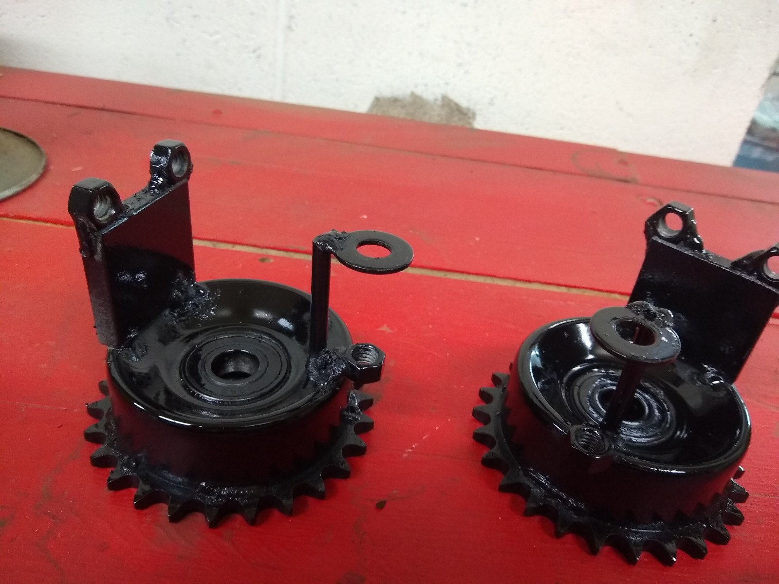
On 7/31/2021 the counter rotating PIE 4.8 was re-phased to have the planet gears synchronized (self-propulsion mode) but then one plant gear was removed from each wheel so that forward pulses will alternate from on side to the other. The non-functioning weights were fastened to the planet gear mounting holes to help balance the wheels a bit.

Results were very similar to having all the planet gears and weights in place and operational with road testing showing a 4% to 6% reduction of engine load at the standard speed of 55 MPH with little to no headwind.

I believe this poor performance may be due to the counter-rotating wheels. Previous testing has shown better thrust using co-rotational wheels (rotating in the same direction). It has been suggested that counter rotation might be needed for stability, especially in either an air or space (aerospace) vehicle, but co-rotation should be very possible with proper management using either air foils or gyroscopes. Co-rotation should still be quite manageable a with minimum amount of manipulation.

8/10/2021 Update

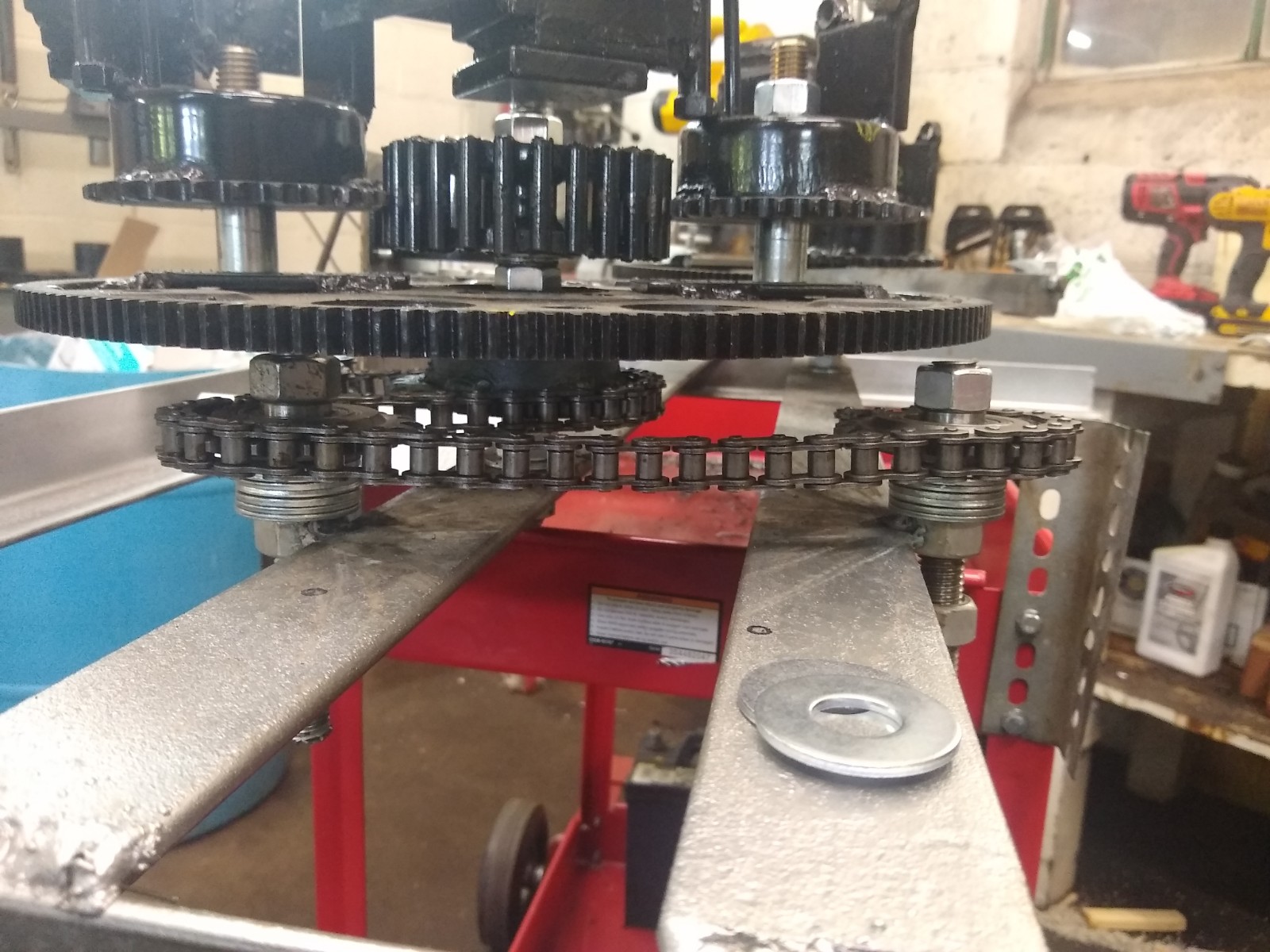
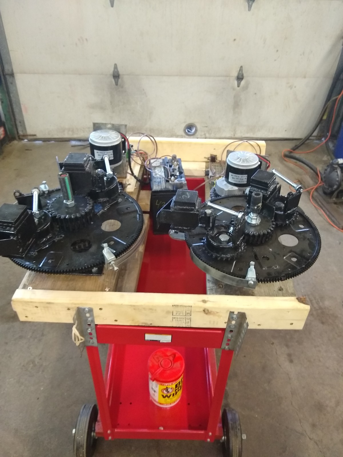
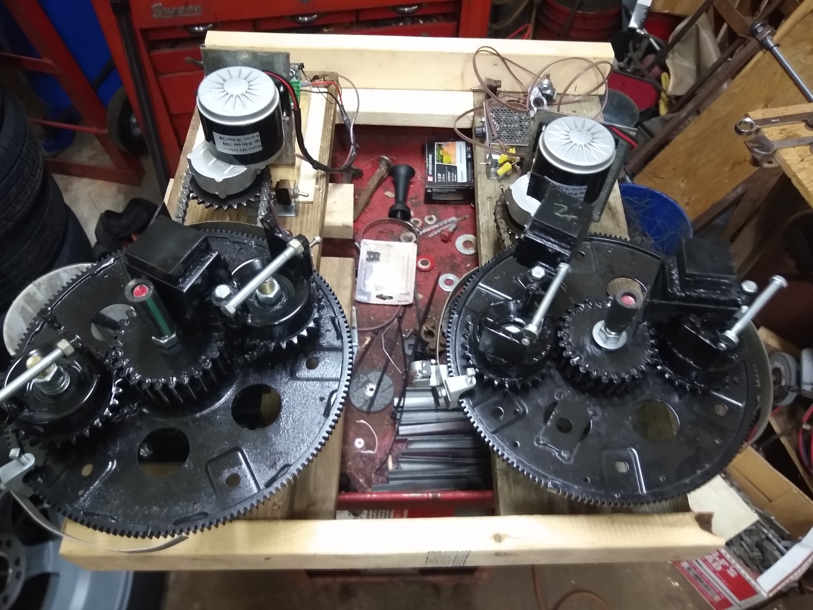
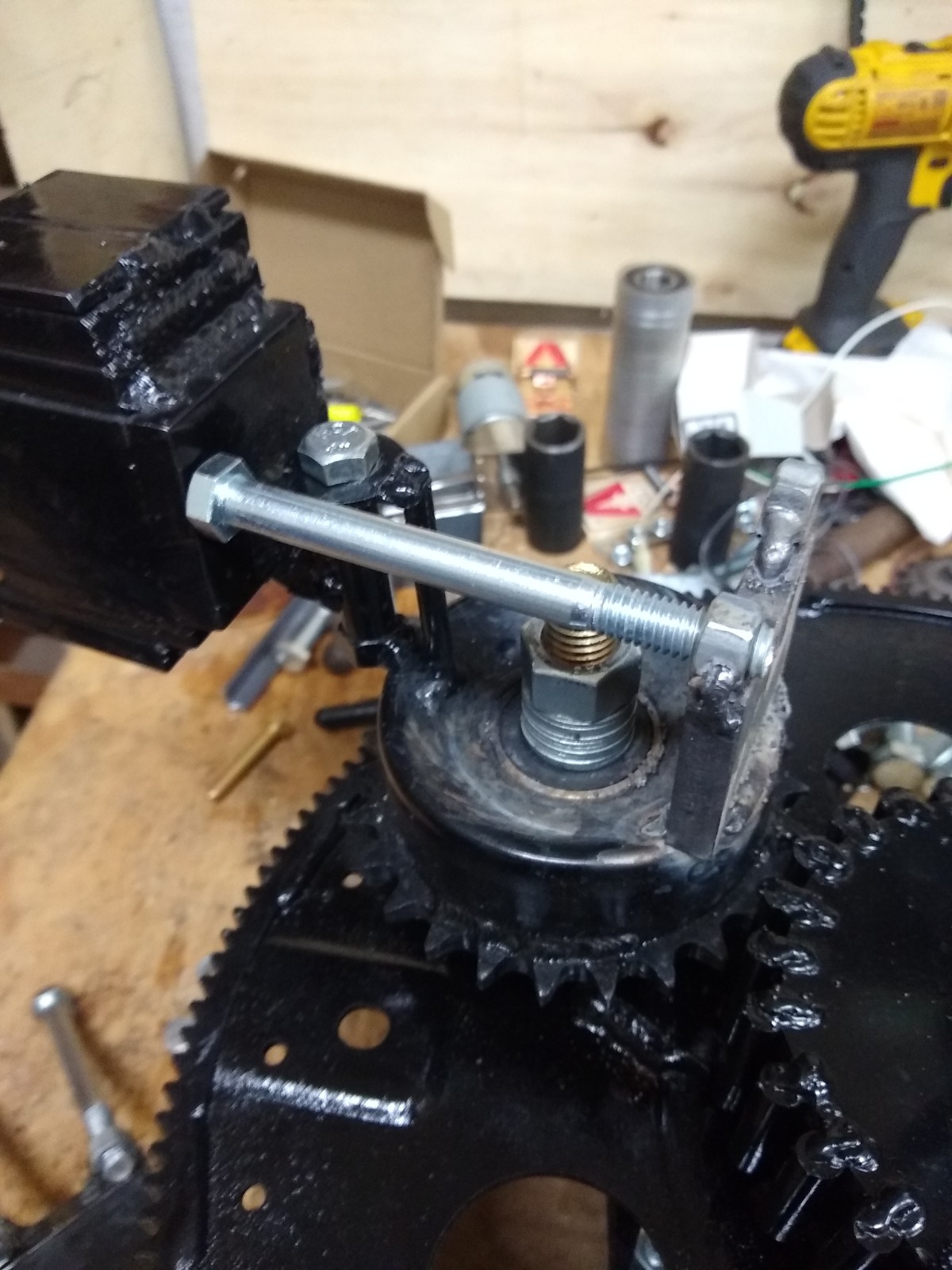
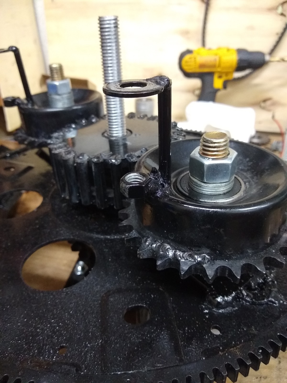
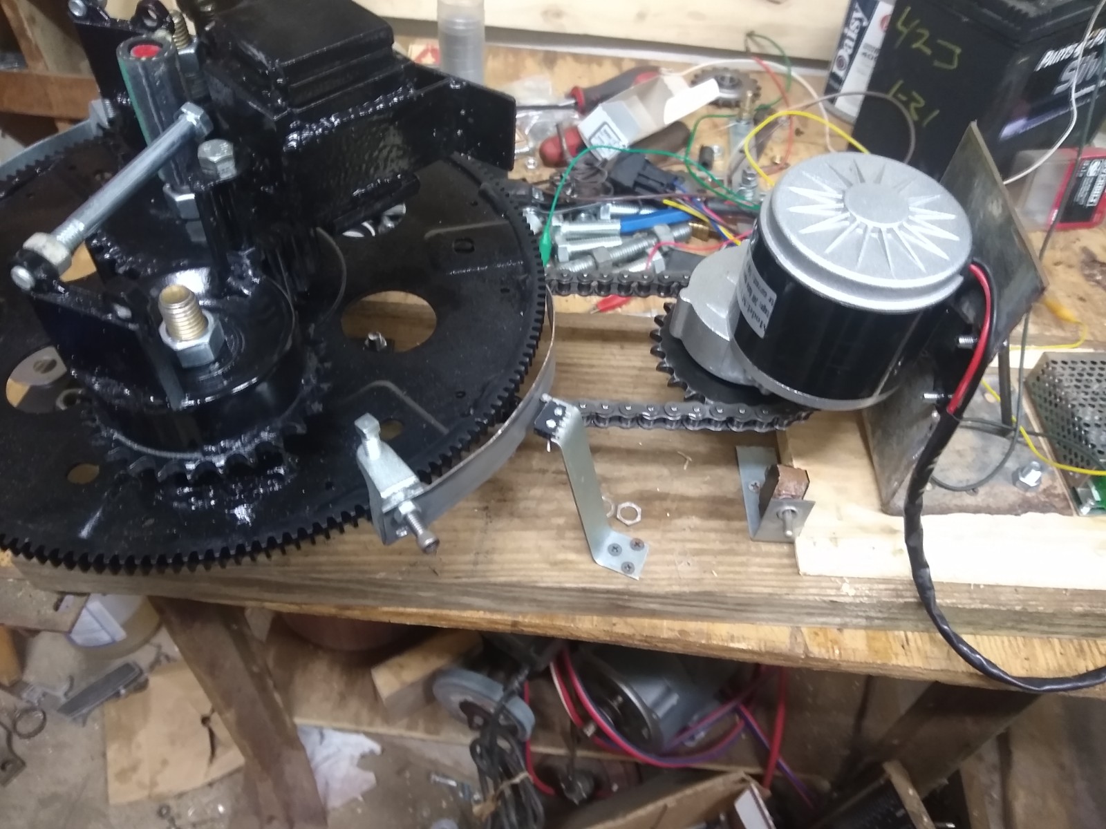
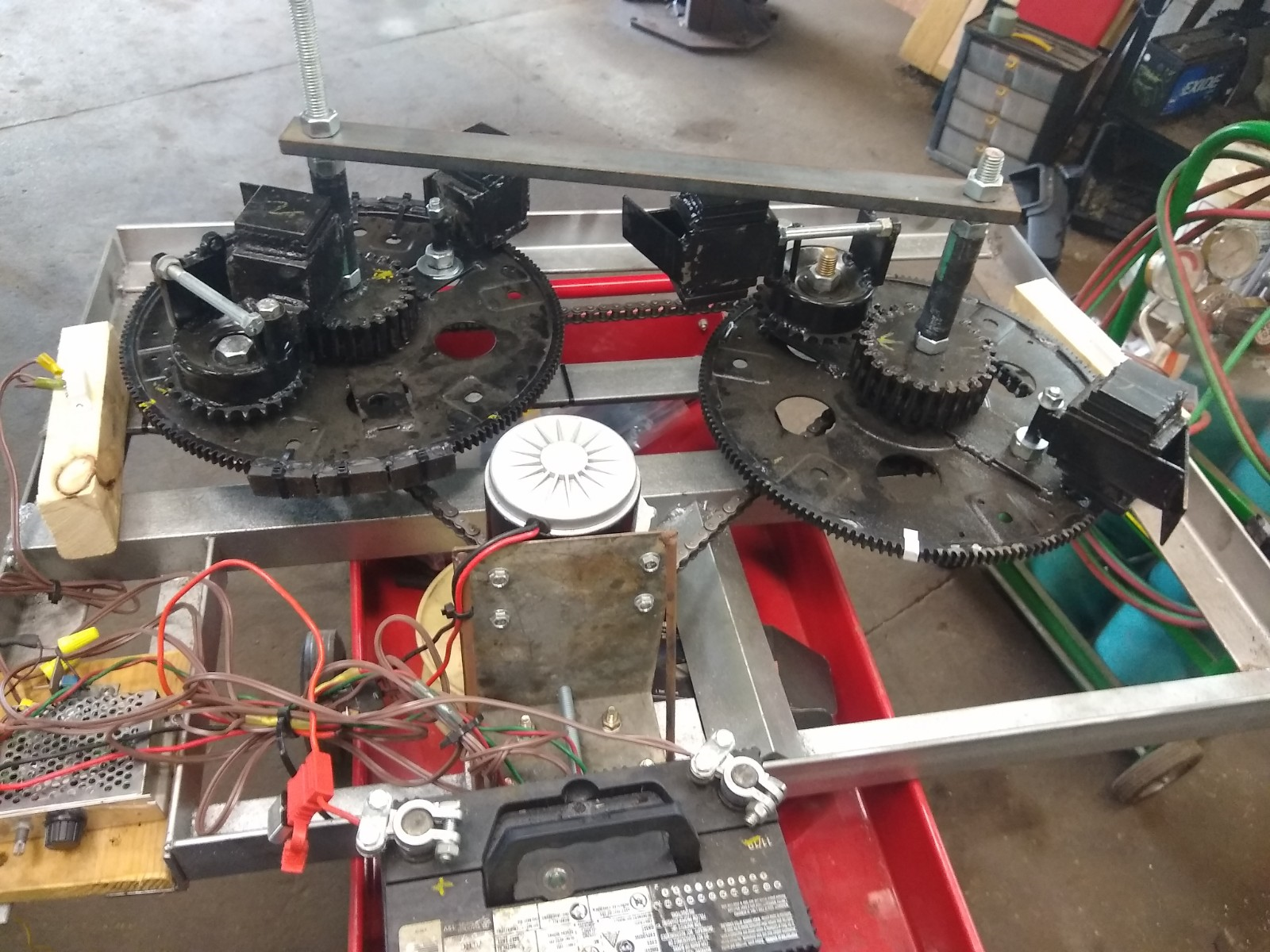
I have now rerouted the chain on the PIE 4.8 so now the Left and Right wheels both turn clockwise, and I have modified the ramp on one of the RH wheel’s weights for the direction change and timed the wheels for self-propulsion (synchronized). With just one weight on the right wheel and two weights on the left wheel I now see that it is a definite improvement over the counter rotating wheel setup!

The first noticeable difference between counter rotating and co-rotating is when counter rotating in this same configuration of 2 weights on left and one on the right the propulsion pulse was strong when a single weight pulsed and weak when two weights synchronously pulsed. With co-rotating wheels the propulsion pulse is strong when a single weight pulsed and doubles in strength when two weights pulse synchronously. In simple terms, the unit is stronger when co-rotational!

I need to put trolley wheels under it again to test properly on the bench, but the unit seems strong and is pulling itself (sliding forward) across the bench when running even without fine tuning the gear timing. Next, I will adjust the gear timing and modify the other weight for clockwise rotation so that I can complete this round of testing.

If there was lots of extra time to do extensive testing it would be best to build it with 4 wheels, two co-rotating and two countering them to be able to arrange them in different ways to record and study the results. I don’t feel it is necessary at this time as the testing I have done is more than adequate to demonstrate the workability of the PIE system.

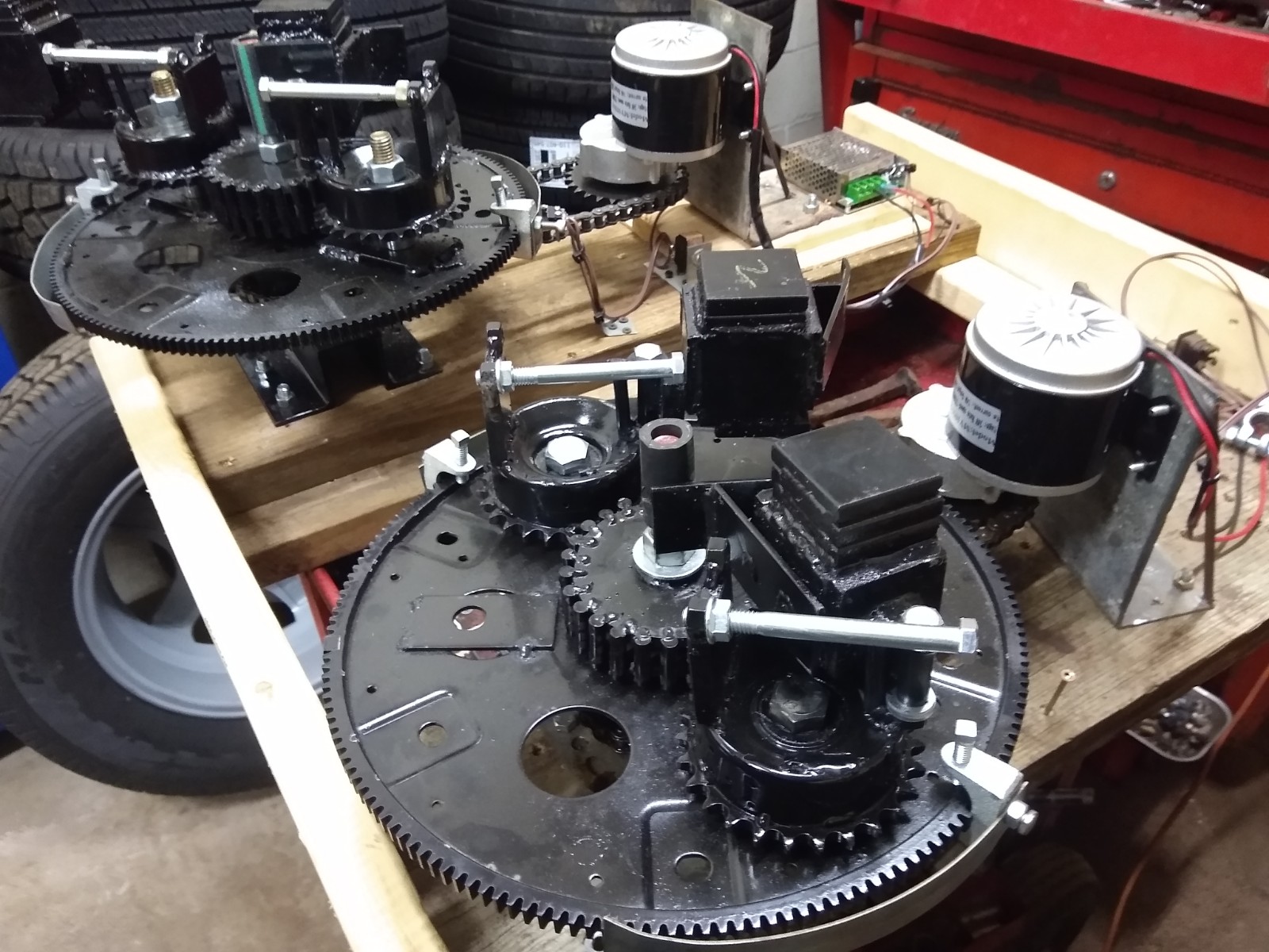
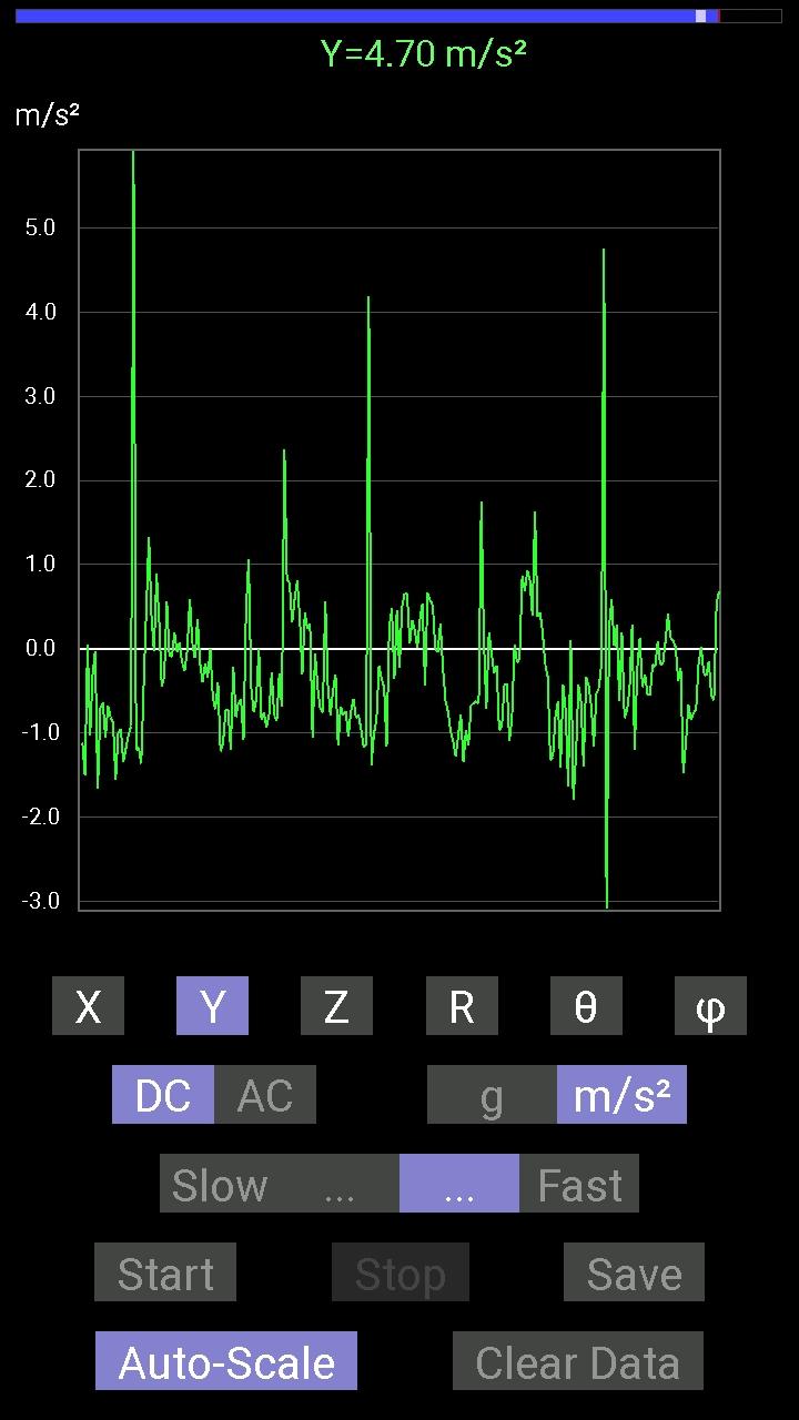
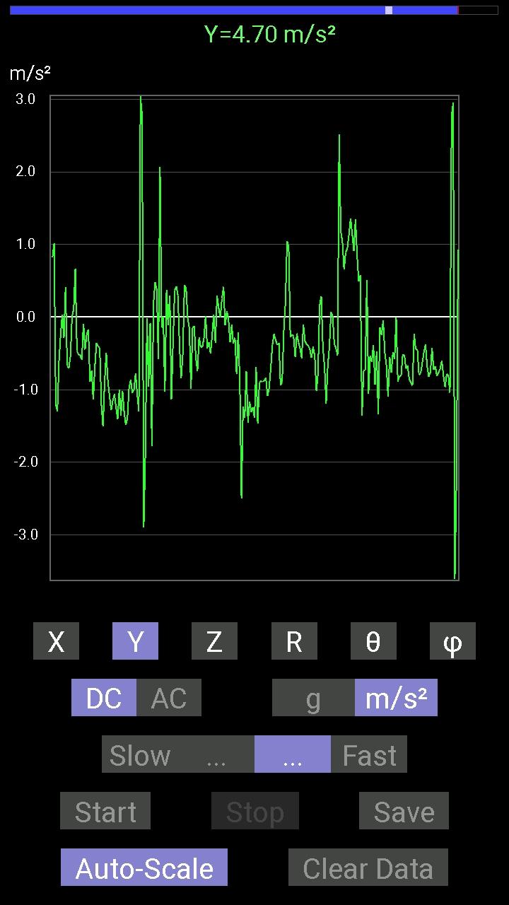
I have discussed the origin of the SDC and the subsequent positive effects of its use, and when I was setting up the PIE 4.8 to co-rotate, I could visually see the point of heavier motor load in the PIE’s rotation. So I published a short video of this visually obvious effect demonstrating the position in rotation which needs the RPM boost using the Speed Differential Control (below).

More to come soon!!!

PIE 4.8 Changes to SDC and Issues on Latest Test Drive

New SDC Switch

It has been a very busy several weeks since I have had opportunity to update this blog. Work and life have been very busy and work on the PIE has been slow.

The re-phased PIE 4.8 has had the first road test completed with no SDC as the SDC micro switch is a continuous source of problems. The lever on the switch tends to break or get bent very easily and the roller wheel also tends to fall off frequently, so it was decided to use a “proximity switch” as a non-contact alternative. The switch chosen is a magnetic switch used for building security systems as a door/window open/close sensor. This is easily activated by mounting magnets instead of mechanical actuators and this works very well.

The PIE 4.8 second test drive was, however, less than outstanding. The re-phased PIE wheels and SDC “should” have yielded much better results than the previously phased tests when it was set up for “self-propulsion”, but the results were very disappointing as the engine load reduction was only in the 4% to 6% range.

I believe it has to do with the counter rotation of the wheels. The “zone of thrust” or “thrust zone” on a single wheel is rather wide as it pulls forward through a good 45 degrees of the rotation, by having the counter rotating wheel, the “thrust zone” is effectively narrowed but instead of “focusing” thrust, it only eliminates part of it.

The next steps to calculate the reason for such failure will be to adjust phasing back to synchronous and increase pulse torque by removing one weight from each wheel. The thrust will alternate between the CW and the CCW wheel, this should demonstrate the theory of the wide thrust angle vs. narrowing the zone.

Phased Back and Switched Down to Two Planet Gears

The non-functioning weight is being used as a balance weight. The planet gear that is not being used is removed and the weight is bolted to the wheel in its place which balances the wheels enough to keep it from tearing itself apart.

One Planet Gear Removed and the Weight Used for Balancing Wheel

If this works out, the plan is to reverse the rotation of one of the wheels and repeating tests with co-rotating wheels to increase thrust without narrowing the “thrust zone”.

Ready For Road Test Set #4

On a side note, I believe the thrust zone will automatically be much more condensed (thus stronger) with a different design. Perhaps the PIE X will accomplish this.

July Update: PIE 4.8, APEC Conference Presentation, Coming Soon – “PIE X” –

July Update:

I just realized that I have not updated this blog in a month, things have been pretty busy around here at Stclairtech R&D.

The PIE 4.8 is fully assembled and functional, I have put on an inertial propulsion presentation for the APEC conference, I have had to move part of our R&D lab to a new location, and actual construction of the PIE X is underway.

PIE 4.8 Testing:

The PIE 4.8 is running through a full gamut of tests where many things are being learned. It is also passing every test so far with very few technical problems.

It is installed in a road vehicle at this time. Below is a quick video getting ready to drive.

I have had smooth enough gearing that there has been no issue holding timing adjustments.

The counter rotating wheels has proven quite successful.

A pendulum type test has been performed successfully. I do not agree that this is truly the “gold standard” that agencies like NASA feel it is since it is easily manipulated. I went to great lengths to ensure accuracy, during which I discovered numerous things which could have skewed the results, reinforcing my belief that a more “foolproof” and “accurate” method needs to be developed. If the PIE did not “pulse” the pendulum test would be much more accurate! A video of the swinging pendulum test is below.

The SDC system works equally as well with 4 actuators allowing the 90-degree offset between wheels which works better as a hybrid design.

Test results will be fully posted here as soon as compiled properly!

APEC Conference:

I narrated a Power Point presentation at the APEC conference on June 26th 2021 regarding the PIE inertial propulsion system and its development from the beginning. The presentation covered development, successes, failures, and equally importantly that I am not trying to “prove” anything. My videos, this blog, presentations, in-person demonstrations, and all testing data is not an attempt to “prove” anything but is simply to “demonstrate” what has been found. What works and what doesn’t work, what is worth investigating and what to work around. A link to the APEC Website and to a video recording of the presentation is below.

Alternative Propulsion (APEC) website

Conference video from 06/26/2021. My part starts at about 3:46 but all are very well worth watching!

PIE X:

Although I have certain obligations to withhold some detailed information regarding the PIE X, I do want to touch on it briefly.

The geometric working design (like the Thornson design) has been presented to me as 2nd and 3rd hand information because the originator is “unavailable” (possibly deceased). There is almost no written information about this design, so much of it is being built from photos taken decades ago and drawings, diagrams, and notes from people who have held this information “in trust” for all these years.

A few details that I can share at this time, the PIE X plans will:

Be a chain driven, electric PIE.

Use 3 “wheels” which for this design will be known as “discs”.

Be able to be mounted in virtually any orientation.

Run at a slightly higher RPM.

Have less obvious “pulsing”.

Be built very heavy (sturdy), with experimental use in mind.

Not use (probably) an SDC control circuit.

Will have more moving parts than the earlier PIEs.

Is much more expensive to construct.

At this writing, the 3 discs are machined, welded, matched, and ready for paint and the framework is partially built and is ready for more components to be assembled. Most of the components have been procured but many of them require customization and there is still much to do!

I wish I could say more and share the PIE X build as openly as the previous builds, but it will be exciting to see if it works as we (my collaboration team and I) believe it will, the unit will be unveiled publicly for demonstrations!!

Until then, stay tuned for more info as it is able to be released!

PIE 4.8 Nearly Ready for Road Testing:

Over the last few weeks, a lot of progress has been made!

The PIE 4.8 CW & CCW halves have been assembled and tested.

 Testing has been done with both running on separate motors at both similar and different speeds, with the conclusion that the halves need to be synchronized to be effective.

A test cart has been constructed with smooth runners to see if the PIE and its wheels were pushing against the wheels’ friction in any way which would indicate a stick-slip drive. Results show that the PIE 4.8 would cleanly self-propel off of the cart under it (which moves as easily as the PIE) without either pushing the cart back or pulling it along. There are those who say that “it proves nothing”, to which I say “OK… I really don’t care! I am not trying to “prove” it works”.

I have a video of that test here:

A new frame has now been constructed for the dual PIE 4.8 and the assembly is almost ready for full-on road testing.

PIE 4.8 frame being assembled

A chain drive was devised to rotate the wheels in opposite directions from a single motor, and the SDC only needs to be connected to one wheel for operation. The frame is pretty heavy being made from 2” X 2” X 3/16” steel angle, but it should not “flex” at all during operation!

PIE 4.8 Chain

Here is a video of the PIE 4.8 being tested on its new frame:

I have also been asked to do a presentation for the APEC conference. I am putting a Power Point (PP) presentation together at this time which I will narrate live rather than pre-recording. There will be graphics (some of which were supplied by Mr. Tokio Muramatsu) and a short “timeline” video… What else is yet to be determined.

More to come as soon as possible!

PIE 4.8 Testing- and -Doubters, Debunkers, and Haters:

Well now, it seems that with the openness of the experimentation, building, fabricating, and functional videos that the “it doesn’t work” folks have become “it only works because of” folks.

The better we get this working, and the more verified data there is, the more people keep coming up with reasons they think we get propulsion. Primarily this presumptive opinion input has revolved around friction. The common theory is that “contact” with virtually anything is the friction causing propulsion. I cannot say that anything is impossible, but short of tossing this thing out into space it will be nearly impossible to “disprove” that theory! Here is my position on this… “Who freaking cares?!?!?!” It just works, so let us expand on this and put it to use for the betterment of EVERYONE!

I get it that the super smart technical theorists believe that anything that isn’t incredibly complex simply cannot work. Sorry people, but that is just another false theory which has been mistaken as fact.

Mine is NOT the only system that works, mine is not the only tech that needs to be openly replicated. If the replications are done with an expectation of failure, it will most likely fail. If they are done with an open & optimistic attitude with an expectation of recording valuable data, extraordinary things are possible!

PIE 4.8 First Test Setup

I have recently published the video on YouTube and BitChute of the first round of Dual-Wheeled testing with fully independent asynchronous control of each wheel (CW & CCW rotating). More testing videos will be published, and a comprehensive report will be published when these tests are complete. That video is visible below.

PIE 4.8 Nearing Test Mode, Science Elitists and Bucking the System, The Dark Side of Science?

I have been actively experimenting and building “stuff” for many years. Some of this “stuff” was really never meant to see the light of day or at least never to be “reviewed” by “academia”, it was done for the sheer joy of creating something new and unique. Now that one of these creations has progressed to the point where it becomes something profoundly useful, academia is pushing back harder than ever… Even with a functional prototype right in front of them, the PhD scientists are quick to expound their firm belief stating loudly “that’s not possible” and accusing anyone involved in any way of being a “charlatan”, a “fake”, or a “scammer”.

Just like the idea of “perpetual motion” or “zero-point energy”, “inertial propulsion” is seen as a direct threat to everything they have been taught and what they have been taught to stand for. Anyone even open to the idea is immediately labeled as a “fraud” and is no longer welcome anywhere near the circles of the “scientifically advanced” or “real” scientists (as they consider themselves).

It has even been publicly stated that “there is no longer a place for the ‘garage inventor’ because there is nothing more they can contribute to science”… HOGWASH! Science has become a cult of “elitists” who are so self-absorbed that all others are too far beneath them to be of any value as human beings…

I have (unfortunately) come into direct contact with these “elitist PhD’s” and have simply learned make peace with this bullshit. Now as people around me are starting to experience the ostracism there seem to be a couple of choices presented. One choice is to “roll over” and “take it up the a$$” by simply shutting up and going away. Another is to “avoid contact” with the elitists and quietly keep working. The third is to “stand and fight” against the system and the elitists running it.

No matter your personal decision, my advice (for what its worth) is to “stay true to what you believe in” BUT always “pick your fights wisely”! That is it… You may choose to avoid conflict and stay “safe”, but if you do choose to “stand-up” to the elite authority, do so wisely and do not expect to unilaterally “win”! Accept the small victories with graciousness, and consider the failures as “learning experiences” the same way we do in the lab or the shop!

Sorry to get so serious… Now I need to get back to work, and do what I do best building stuff… Thanks for reading this!

–The PIE 4.8 is ready to test with two counter rotating wheels. The two wheels are fully independent with their own identical speed controllers and motors. They are fastened together on a 2X4 frame, and initial testing will be on wheels followed by on-road testing. The photo has the assembly sitting on a work cart. That cart is not stable enough to run the PIE on, but it is enough to load/unload it from its transportation, and carry it between test stands.

PIE 4.8
PIE 4.8 CW & CCW Rotating Wheels Ready for Testing Together

PIE 4.8 Dual Assembly

PIE 4.8 – The APEC 5/1/2021 Conference and the “Inertial Doppler Effect”

The PIE 4.8 CCW wheel is pretty well set. I have attempted to get some force tests done with a force meter, the output readings were very unstable at best. I was however able to get some slightly better readings with an accelerometer.

The photos are screenshots from an accelerometer app on an android phone. The waveform or trace is below the “0” when pulling forward. It is obvious that there is a more stable pull during each pulse forward, and disorganized spikes in the reversion direction. Keep in mind that it will show a small reverse pull between forward pulses just because the chassis slows slightly between propulsive pulses.

On Saturday 5/1/2021 I had the honor of being asked (at the very last minute) to speak about the PIE systems on the APEC conference Zoom meeting. My part was near the end but just before open discussion at 4:51:28 and even though I did not have anything prepared it was still a lot of fun. APEC is Advanced Propulsion Engineering Conference and it is hosted by Tim Ventura of American Antigravity (https://www.americanantigravity.com). The full video of that conference is here:

During the conference we talked about the PIE systems, discussed theory, and talked about the near-future testing. We also discussed a phenomena that has been showing up in PIE experiments since the first on-road tests of the PIE 1.0. The phenomenon is that of increasing thrust when the entire unit is in motion. The faster the test vehicle moved the more forward thrust was experienced with each pulse. This has also been experienced and proven in the lab, so it has moved from a possibility into a fully testable repeating phenomenon. For lack of any better analogous terminology I started calling this the “Inertial Doppler Effect”. As a friend and colleague was maintaining that he thought the PIEs are still some form of “stick-slip” drive which depend on friction to operate (fully disproven in the lab) and it occurred to me that maybe he is wrong and right at the same time.

This is my current understanding of this phenomenon. I know that my “loose definition” of Doppler is not 100% correct when comparing a mechanical system to an EM wave form. This is a copy and paste of my reply to the idea of the PIE being a stick-slip drive:

My analogy of inertial Doppler is a “still forming” theorem, bit it currently a spacial/mass/inertial interaction which is proving itself in reality. Here are some cold, hard, facts… Doppler effect exists because the “center of mass” of the energy wave is moving and the energy is emanating from that “center of mass” making the wave have more “force” in the forward moving direction (Overly Simplified). Sooooo… The PIE (or I venture to say “any”) inertial drive will exhibit the Doppler effect, and if that is so (it is IMO) then all inertial drives ABSOLUTELY MUST have more mass in the overall structure than the masses being displaced (moved, oscillated, etc. also) in order to have directed thrust (linear motion). If the mass of the structure were less there would only be massive vibration (oscillation) – example: if a 2 moving mass (weights) structure weighed 5kg and the masses weighed 2.5kg each there would be a net linear propulsion of little more than zero even if the propulsive force was 2X higher than reversion force, but if the structure weighed 10kg there would be more mass “in motion” than there is “reverting”… So, ideally the mass of the structure should be 1 to 2X of the reversion force!

If I didn’t ramble too incoherently, and you are following my train of thought above, this means that ANY inertial drive which succumbs to this theory is a “stick-slip” drive but it is the inertia of the structure’s mass that it’s “sticking” to (pushing against). It also explains the Doppler effect because if it is “pushing” against inertia itself, that inertia is stronger as the structure moves!

I may have sprained a brain cell or two trying to put this theorem into words!!!

Till next time….

PIE 4.7 is now the PIE 4.8 with Thrust Test Video

The PIE counterclockwise wheel (CCW) is nearly finished and will be tested very soon. I made a significant change to the “outer stop” which works so well to warrant changing up the model number to PIE 4.8 and I am installing them on all of the planet gears for the PIE 4.8.

improved outer stops and “Halo” mounts after painting

Halo mount and improved outer stop as seen during setup

I have also improved the mounting (resembling a halo) for the swinging weight. This improvement also allows for the addition of strengthener braces if it is found to be necessary.

Halo Bracket for Swinging Weight

The new stops allow for actual adjustment of the stops. This will allow me to make small changes to stop position and find out if there is a particular “sweet spot” for the outer stop.

Improved outer stop and halo mount working well during SDC setup

The CCW wheel is constructed to run on its own with its own separate motor and speed controller (as seen above). This is necessary to run the full gamut of necessary tests regarding phasing and RPMs. Once these tests are complete there will be better data regarding proper synchronization and whether the two opposing wheels should even be synched at all.

I have posted several videos on my YouTube and BitChute channels showing the building of the CCW and the new PIE 4.8 stops. Here (below) is the new PIE 4.8 CCW running its bench test with the SDC installed.

Here (below) is the first bench test run of the CCW before the SDC was installed.

Here (below) is the PIE 4.8 CCW set on some pipe rollers just to check for backward force (reversion) vs. forward force (thrust).

First Thrust bench Test of PIE 4.8 CCW Assembly

PIE 4.7 and “PIE X”

PIETECH 4.7 and “PIE X”:

It has been a while since my last post, or video so here is an update:

The PIE 4.7 second half (CCW wheel) is progressing, although somewhat slower than I would prefer as life’s circumstances have presented certain obstacles to its advancement. The first “dead blow” weight for it is ready to install, and another is in process.

I always said it is not a good idea to have more than one project going at a time, yet that is exactly what I am doing…

After communicating at length with other builders, I have split my time between the PIE 4.7 and a new design, the “PIE X”. It has some radically different internal components and will look a bit different but it is still what I would call a Pulsed Inertial Engine, so right now it is known as the “PIE X”.

This design has originated from other people so I will need their permission to “open source” any of that information! I require their permission to share or publish the information leading up to the PIE X without the consent of those who have been kind enough to share the basic design information with me!

If the PIE X is as feasible as predicted and becomes something worth pursuing more information may be provided (with permission), and if it falls short, I will provide thoughts regarding that failure (still, with permission only).

Note: The PIE X is quite a bit more expensive and much more complex to build and fabricate the components for, so it may not be something the casual hobbyist would feel comfortable with, at least not until there is a working prototype to prove the principals.

Those who know me and those who have followed along with my PIE/PIETECH projects know that I do not randomly spout “theory”. I only present factual information so until I have an experimental prototype, I would not request permission to elaborate any technical information. I only mention the PIE X as an ongoing project because it does slow the PIE 4.7 project and has pushed back the timetable to begin full testing. I am hoping to be performing “on road” testing of the PIE 4.7 by early June which gives me about 8 weeks.

I hope to be posting photos and videos VERY soon, so right now I need to go get busy, I have a PIE 4.7 to finish building and a PIE X to get underway!

Starting the PIE 4.7 Second Wheel

I am now actively building more weights and components for the counter rotating wheel assembly. As we have seen before, the PIE design works better with two wheels but this is the first one that has “self-propelled) with just one wheel. I think it will be very interesting to see it work with a second wheel, especially a counter rotating one.

If I do decide that I do not want it to counter rotate, the weights can be modified by just grinding the welds for the ramp brackets that I welded to the side of each one. The pivots are being made to work with the stops in either direction. The other pieces that would need changing are really just the actuators for the switches, so it would not be a super big deal.

It has been a little while since the first half was built, so I did have to go back and look to make sure the new weights match the original ones in both size and weight. Eight 2X2X3/8″ steel squares, two 1-1/2X3X1/16″ rectangles, a block to hold the pivot bushing and the bushing itself. Once the basic box is made, the BB’s are added to complete the weight measurement and make it a dead blow. I thought they were 2 kg each, but I actually had to weigh one to be absolutely certain! Once the BB’s are added, the top is welded on, and it will need a coat of paint.

The wheel is already constructed, as is the sun gear, so some of the most time-consuming work is already done.

I will update the blog here, as it all progresses.